- Figure 1.3 This two mirror "Clock" sends to the eye flash after flash each seperated from the next by 1 meter of light travel time. A light flash (represented by an asterisk) bounces back and forth between parallel mirrors separated from one another by 0.5 meter of distance.
- Page 12 also defines what one tick is:
- Such a device is a "clock" that "ticks" each time the light flash arrives back at a given mirror.
-
In the following text we use the center of the clock as this reference point.
The same clock, based on light flashes, is also used in our experiments.
At page 12 we also read:
-
In 1983 etc. The meter is now defined as the distance that light travels in a vacuum in the fraction 1/299,792,458 of a second.
Since 1983 the speed of light is by definition equal to c = 299,792,458 meters/second. -
This raises immediate certain questions: Why define the speed of any photon as constant? What has a vacuum to with the speed of a photon? What is a vacuum? At which place in the universe there actual is a vacuum?
To start with the last question: in a laboratory we can create a vacuum. In principle you can calculate the speed of light in that vacuum, but does that say anything about the speed of a photon travelling between the Sun and the Earth? I doubt this.
Just a thought.I want to emphasize that there is nothing wrong to define the speed of light equal to 299,792,458 meters/second. Solely for pratical purposes. As such you can also use c=1
What is wrong to claim that the speed of light has a (physical) constant speed and the claim that this is true in vacuum, without any explanation. Why not mention that this is only true outside any gravitational field?An important experiment discussed in the book is: how to synchronize several clocks in the lattice. This is described at page 37. Here we read:
- Pick one clock in the lattice as the standard and call it the reference clock. Start this reference clock with its pointer set initially at zero time. At this instant let it send out a flash of light that spreads out as a spherical wave in all directions. Call the flash emission the reference event and the spreading spherical wave the reference flash
-
What I will demonstrate is that this concept of reference flash is in reality very complex.
At page 38 we read: -
In this case the second method of synchronization etc.
Moreover, the error can be made as small as desired by carrying the portable clock around sufficiently slowly. -
The error in the clock reading is based on the extra distance travelled.
There are two more issues that require our attention: At page 53 we read:
- How do you know you are moving? or at rest?
- The question is what does this has to do with the laws of nature. Specific what has my state, the state of an observer, has to do with physics. IMO nothing. There are two more issues that require our attention: At page 55 we read:
- A ball untouched by force undergoes no acceleration.
- Also at page 55 we read:
- All the laws of physics are the same in every free-float (inertial) reference frame.
-
The first question to answer is: what are all the laws of physics? Is there a list?.
Do they mean: All physical processes behave the same in every free-floating reference frame? That means processes instead of laws.
The problem is there exist no free-floating objects. All objects in space undergo acceleration. Maybe it is small, but they are all influenced by some force or another.This same problem is also discussed at the pages 30-32.
At page 31 we read: -
the two particles move farther apart as the coach falls. Conclusion: the large enclosure is not a free-float frame
and: Free-float frame is local. -
But this exactly describes the problem: What are the laws that describe the two particles. What are the laws that describe the movement of the planets around the sun?
The biggest problem with Newton's Law is that gravity does not act instantaneous.
At page 34 we read: - When tests of gravity are very sensitive or when gravitational effects are large such as near white dwarfs or neutron stars then Einsteins predictions are not the same as Newton's. etc. This justifies Einstein's insistence on getting rid of gravity locally using free-float frames.
-
The most important subject is this document are processes (experiments) when acceleration is involved and the laws that describe these processes (experiments)
(1)
At page 63 we read: -
Figure 3-1. Einstein's Train Paradox illustrating the realtivity of simulataneity.
Top: Lightning strikes the front of a moving train etc
Bottom: Observer O standing by tht tracks halfway between the char marks on the tracks concludes that the strokes were simultaneous, since the flashes from the strokes reach him at the same time. -
The only thing that the observer O sees, is that the two flashes reach him simultaneous and if that is true then ofcourse observer A on the moving train, cannot see the two flashes simultaneous
What Observer O cannot claim is that the strokes were simultaneous. Observer A on the train has exactly the same right to make this claim. Observer B on a different train also could claim this. Infact if there are many trains in the same situation as depicted in the Top Figure only one can make this claim.
This whole experiment is excessive discussed in paragraph 6 and 7.
1. Introduction
This document discusses the behaviour of a clock in a linear accelerator a and centrifuge.The clock used is explained in the book "Space time Physics" by E.F. Taylor and J.A. Wheeler Second Edition.
At page 12 of this book we read:
2. The clock
-
The clock in the book "SpaceTime Physics" at page 37 consists of 6 mirrors. Two parallel mirors in each x,y,z direction. (2*3=6)
The clock in our experiments uses 4 mirrors. Two parallel mirors in either the x,y or x,z direction.
In the book the flashes are both reflected and can go through the mirror. Here only reflection is discussed.
The flashes are generated in the center of the box.
Depending on the direction of movement, a clock can operate in either two ways: Parallel or Perpendicular.
A clock is called Perpendicular when the mirrors are Perpendicular in the direction of movement. The flashes are generated in the center in the horizontal direction (towards the right and the left). From the viewpoint of an observer in a train the flashes are reflected in the front and the back of the train.
A clock is called Parallel when when the mirrors are Parallel in the direction of movement. The flashes are generated in the center in the vertical direction and from the viewpoint of a moving observer reflected from above and below (the ceiling and the floor). In the case of a centrifuge: the outside and the inside.
One cycle of a Perpendicular clock means that the flash starts in the center, moves towards the in the front, is reflected, moves towards the mirror in the back. The cycle ends when the falsh reaches the center. Then the next cycle starts.
One cycle of a Parallel clock is the same except that the flash is reflected at the top and bottom mirror. (or the reverse)
3. Experiment with a clock and a linear accelerator
-
The first experiment we want to discuss is the behaviour of a clock in a linear accelerator.
This behaviour is described in figures 1, 2,3 and 4
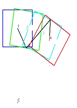
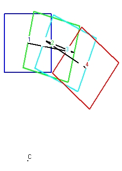
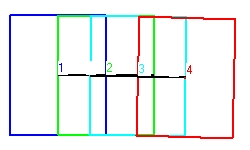
- Figure 1 shows the behaviour of a clock with perpendicular mirrors. The clock moves towards the right. The light signal moves in horizontal direction.
There are two ways that the clock can operate, starting from the center of the clock:
- First the light signal moves towards the left. When it reaches the left mirror it bounches back towards the right mirror. Again it bounches back towards the left untill it reaches the center of the clock. This defines one cylce or one tick of the clock. All this movement is in the horizontal direction.
- The second method is almost identical as the first, except that the intitial signal moves towards the right. For the rest the two are identical.
The next position is indicated with point 2. The shape of the clock is in light green. The situation indicated shows the exact point of reflection against the left mirror. This position is more towards the right because the clock moves towards the right.
The next position is indicated with point 3. The shape of the clock is in magenta. The situation indicated shows the exact point of reflection against the right mirror. This is along trajectory because both the mirror is at the right side and the clock moves towards the right.
The final position is indicated with point 4. The shape of the clock is in redish brown. The situation indicated shows the exact point when the flash reaches the . This is short trajectory because both the mirror is at the center at the left side and the clock moves towards the right.
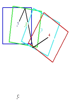
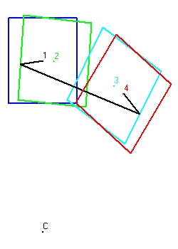
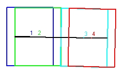
Figure 1 is rather difficult to follow. Figure 2 is easier. - Figure 2 shows the behaviour of a clock with parallel mirrors. The clock moves towards the right. The light signal starts with an angle of 60 degrees.
There are two ways that the clock can operate, starting from the center of the clock:
- First the light signal moves towards the ceiling with an angle of 60 degrees. When it reaches the ceiling mirror it bounches under an angle of 300 degrees towards the bottom mirror. Again it bounches back towards the ceiling under an angle of 45 degrees untill it reaches the center of the clock. This defines one cylce or one tick of the clock.
- The second method is almost identical as the first, except that the intitial lightsignal signal moves with an angle of 300 degrees towards the bottom and then it bounces back towards the ceiling. For the rest the two are identical.
The first cylce is indicated with the numbers 1,2,3 and 4. The second cycle with the numbers 4,5,6,and 7. The third cycle with the numbers 7,8,9 and 10. and the fourth with the numbers 10,11,12 and 13.
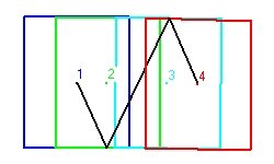
The numbers 1,4,7 and 10 each indicated the center of the clock. This is important. - Figure 3 shows a clock with perpendicular mirrors in a linear accelerator. The light signal moves horizontal.
Figure 3 shows 4 cycles. The first cylce is indicated with the numbers 1,2,3 and 4. The second cycle with the numbers 4,5,6,and 7. The third cycle with the numbers 7,8,9 and 10. The fourth cycle with the numbers 10,11,12 and 13
What the cycles shown is the increase in speed.
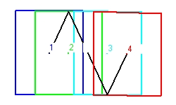
- Figure 4 shows a clock with parallel mirrors in a linear accelerator. The light signal more or less moves zig zag.
Figure 4 shows 3 cycles. The first cylce is indicated with the numbers 1,2,3 and 4. The second cycle with the numbers 4,5,6,and 7. The third cycle with the numbers 7,8,9 and 10. and the fourth at the numbers 10,11,12 and 13
What the cycles shown is the increase in speed.
What is missing is what is happening in the initial state of the clock with v=0. With v=0 Figure 4 should show a vertical line through point 1.Figure 4 shows 4 cycles. The 4 cycles start at the points 1,4,7 and 10. What is important that the angles of emmission are different.
With v = 0 this angle is 90 degrees. At point 1 with v=0.1 the angle is 84.26 degrees. At point 4 with v=0.3 the angle is 72.541 degrees. At point 7 with v=0.5 the angle is 60 degrees. At point 10 with v=0.7 the angle is 45.573 degrees.
For technical details see: Technical Data - Figure 4
In the figures 1 and 2 the speed is constant. In the figures 3 and 4 the speed is increasing.
Perpendicular mirrors - v=0.5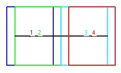
|
Parallel mirrors - v=0.5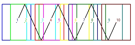
|
For technical details see: Technical Data - Figure 1 and Technical Data - Figure 2
For more technical information see: Reflection 3 - The physics of a clock
Perpendicular mirrors - v increasing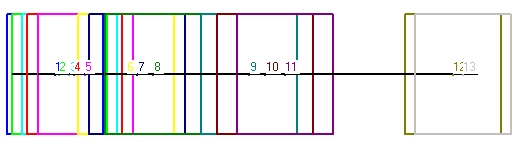 |
The initial speed is 0.1*c. The next speeds are 0.3*c, 0.5*c and 0.7*c.
For technical details see: Technical Data - Figure 3 Figure 4 is more interesting.
Parallel mirrors - v increasing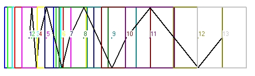 |
The question is how does a clock with either perpendicular or parallel mirrors performs this task? The behaviour of parallel mirrors is for sure the most difficult.
In reality the clock is much smaller and moves slowly from v=0 to v=0.5. The question remains the same.
4. Experiment with a clock inserted in a centrifuge
-
In the following simulates the clock is inserted in the centrifuge. The centrifuge rotates in clock direction and the speed in all cases is 0.5 times c.
- Figure 5 shows a simulation of three full cycles for a clock with perpendicular mirrors. The first reflection is towards the left mirror (mirror #1)
- Figure 6 shows a simulation of three full cycles for a clock with parallel mirrors. The first reflection is towards the top (mirror #3). The initial angle is 45 degrees.
- Figure 7 shows a simulation of a full cycle for a clock with parallel mirrors and when the first reflection is towards the floor (mirror 1)
- Figure 8 shows a simulation of a full cycle for a clock with parallel mirrors and when the first reflection is towards the top (mirror 3)
- Figure 9 shows a simulation of a full cycle for a clock with perpendicular mirrors and when the first reflection is towards the right (mirror 2)
- Figure 10 shows a simulation of a full cycle for a clock with perpendicular mirrors and when the first reflection is towards the left (mirror 4)
- Figure 11 shows a simulation of a full cycle for a clock with parallel mirrors and when the first reflection is towards the floor (mirror 1)
- Figure 12 shows a simulation of a full cycle for a clock with parallel mirrors and when the first reflection is towards the top (mirror 3)
- Figure 13 shows a simulation of a full cycle for a clock with perpendicular mirrors and when the first reflection is towards the right (mirror 2)
- Figure 14 shows a simulation of a full cycle for a clock with perpendicular mirrors and when the first reflection is towards the left (mirror 4)
Perpendicular mirrors v= 0.5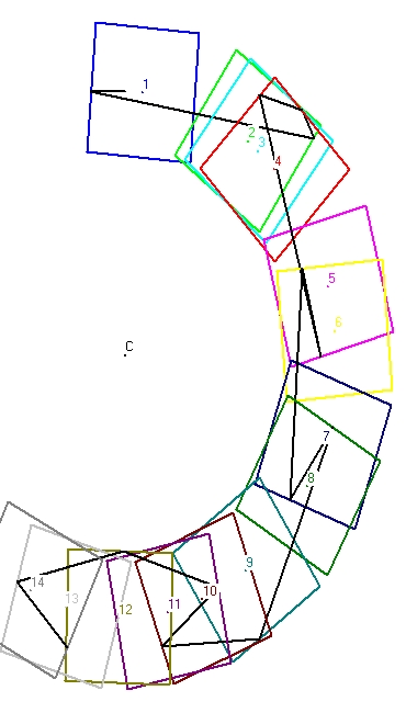 |
Parallel mirrors v = 0.5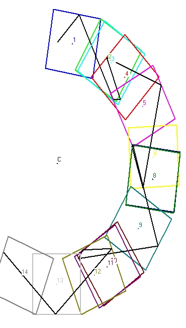 |
A Long simulation starts in the center in a certain direction. The first reflection is either against mirror 1, 2, 3 or 4 and the continues from there on.
For technical details see: Technical Data - Figure 5 and Technical Data - Figure 6
For more Long simulations select: Clock and Centrifuge part2
Parallel mirrors
 |
 |
To observe the same but now for 4 cycles select: Experiments with a clock inserted in a centrifuge - 4 Cycles
Perpendicular mirrors
 |
 |
To observe the same but now for more cycles select: Experiments with a clock inserted in a centrifuge - 4 Cycles
Parallel mirrors
 |
 |
Perpendicular mirrors
 |
 |
5. The simulation program
-
In order to do the simulations there are two programs: "VB Draw" and "Draw_Research".
- Main, Simulation, Linex, Clock and Distance
-
The calling order is rather simple: Main calls the subroutine Simulation (in a loop). Simulation calls Linex (in a loop). Linex calls the subroutine Clock (in a loop) and Clock calls Distance (in a loop).
- The subroutine Distance calculates the distance between the position of the flash at a certain moment and one specific mirror.
There a 4 real mirrors and 2 virtual mirrors. The 4 real mirrors are identified with the numbers 1 to 4. #1 is the bottom mirror. #2 is the right mirror. #3 the top or ceiling mirror and #4 the mirror at the left side.
The two virtual mirrors are positioned at the center of the clock. #5 is a horizontal mirror and #6 a vertical mirror.
The distances calculated are stored in an array.
- The subroutine clock calculates
- First the positions of the 4 mirrors as a function of the time, the speed and hardware used (Linear Accelerator OR Centrifuge. These positions are stored in two x() and y() arrays.
The same is also done for the two virtual mirrors. - Next the subroutine calculates the distance between the flash at a certain moment and each of the 6 mirrors.
- First the positions of the 4 mirrors as a function of the time, the speed and hardware used (Linear Accelerator OR Centrifuge. These positions are stored in two x() and y() arrays.
- The subroutine Linex calculates the straight path length of a flash, from start to finish.
That means:- from emmission at the center to next reflection or
- from the previous reflection to the next reflection or
- from the previous reflection towards the center of the clock.
Input parameters are the angle of the flash and the start time.
Output parameters are the length of the flash and the duration.
The most difficult part is to calculate the reflection point (or moment of reflection) as accurate as possible.The subroutine works in two modes: rough and optimization.
In the rough mode the step size is fixed (0.1) . In the optimization mode the step size varies.
Generally speaking in each loop of the program three parameters are calculated:- The time of the event. The position of the flash, and the distance towards the mirror.
The distance is calculated in the subroutine clock- The time and the distance are stored each in a array of length 4. In the rough mode at each loop cycle first the old values in each of the arrays are shifted towards the left and the two new values are stored in position 4.
In the rough mode the 4 distance values will slowly decrease. The rough mode stops when the value in position 4 starts to increase. That means the flash is outside the clock limits.
For example the 4 distance values can be 7, 4, 1 , 2 at time values: 10, 10.1, 10.2 and 10.3.
The next cycle is now performed inbetween the distance values 4 and 1 with the time value 10.15.
An alternatif selection could have been inbetween distance values 1 and 2 with the time value 10.25.
In both cases the step size decreases to 0.05. The subroutine stops when the step size becomes below a certain limit.- The subroutine Simulation calculates the length of the path of a full cycle. That means from the center of the clock (point 1) towards the first reflection (point 2), towards the second reflection (point 3) and back towards the center (point 4).
The center is also implemented as a mirror. (in fact 2 mirrors). The final parameter output parameter is the distance from the center.
The 4 points mentioned here are the same as the 4 points in each simulation. There are 3 modes of simulation: Short, Long and Linear. In the Short and Linear mode the subroutine strictly one cylce (4 points) is calculated. In the Long mode the simulation continues. See the Figures 5 and 6.- The subroutine Simulation calculates the path length of a flash from the center of a clock towards the center, but does generally speaking not touch the center. The subroutine Main calculates calculates the true distance.
Input parameter is a mirror to select to initial angle. When the mirror is 1, the initial flash will go down. When the mirror is 2 the flash will go towards the right. With 3 up and with 4 left. The next step is a similar optimization as explained in Linex. The parameter to minimize is the shortest distance between the position of the flash and the center. The control variable is the initial angle of the flash.
It should be mentioned that in the simulation program the concept of SR is not used.
What is simulated is the internal functionality i.e. the length of the flash between reflections. - The subroutine Distance calculates the distance between the position of the flash at a certain moment and one specific mirror.
"VB_Draw" is a visual basic program to simulate the behavior of a clock in both a linear accelerator or centrifuge. Its basic inputs and outputs are come of what is called a form.
"VB_Draw" is an Excel program to simulate the behavior of a clock in both a linear accelerator or centrifuge. Its basic inputs and outputs are come of what is called a spread sheet.
From a mathematical point of view both programs are identical. The difference is in the man machine interface.
The program consists of a number of subroutines which have the folowing names:
6. Train experiment from the perspectif of Observer O (platform at rest)
-
Consider an observer O at a platform near the tracks of a train.
- At a certain moment almost 'simultaneous' lightning hits the tracks at the left side and the right side of observer O. These two events, (1) left and (2) right create a special lightflash ( a ball of light) which observer O sees simultaneous. This we call event (3) .
It is important to stipulate that what observer O sees are the two flashes when they reach the observer O i.e. event (3). What observer O does not see are the two events (1) and (2) when lightning strikes the tracks. These points are called the points of contact.
- Exactly at the same moment when observer O at the platform sees event (3) also a train passes from left to right. At the train there is observer A which position coincides with observer O when event (3) happens. That means also observer A observes the two events (1) and (2) simultaneous.
- Exactly at the same moment when observer O at the platform sees event (3) also a train passes from right to left. At the train we have observer B which position coincides with observer A when event (3) happens. That means also observer B observes the two events (1) and (2) simultaneous.
- That means all the three observers see event (3) simultaneous.
Of course such an experiment is difficult to perform in reality, but it is not impossible. -
The us assume that observer O stands exactly in the middle of the two points of contact at the platform.
Next you ask the two observers: Is each of you standing exactly in the middle between the two points of contact. This is depicted in Figure 15.
Suppose they all give the same answer: "Yes". The problem is: this can not be physical true
Figure 15 "General" shows the unrealistic situation when all observers answer: "Yes".General
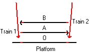
Figure 15 Event (1) and (2)
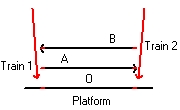
Figure 16 Event (3)
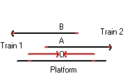
Figure 17
Figure 16 "Event (1) and (2)" shows the position of the trains when lightning hits the trains.
Figure 17 "Event (3)" shows the position of the trains when the lightning is observed simultaneous by the three observers O, A and B. -
To understand why not all the observers can stand in the middle let us assume that observer O actual stands in the middle of the two points of contact.
This situation is depicted at figure 1 when lightning strikes both the platform and two trains i.e. the events (1) and (2).
The points of contact are the 6 small red lines (markers), 1 left of each observers and 1 right of each observer
The three left markers are at equal distance. They all indicate event (1). The three right markers indicate event (2)
What is important that at the moment when these two events happen observer A, standing on train 1 is left of Observer O. Observer B, standing on train 2 is right of observer O. -
Figure 16 shows the situation when each observer actual sees the moment when lightning hits the trains. These two signals are indicated by the two horizontal lines. One signal originates from event (1) and one signal signal originates from event(2)
All the three observer see this simultaneous. This is indicated because the observers A and B are at the same position as Observer O
The situation in Figure 17 is later as the situation as in Figure 16.
During that period the train A has moved towards the right. That is why observer A is drawn towards the left in Figure 16
During that same period the train B has moved towards the left. That is why observer B is drawn towards the right in Figure 16
- To chalenge this answer let us first simplify the experiment and make it more symmetric.
Let us assume that each observer stands in the middle of a long flat train. Each train has the same length.
That means the platform train of Observer O stands still. It has a speed v= 0.
The train 1 of observer A has a speed v>0 to the right, relatif to the platform train
The train 2 observer B has a speed v<0 to the left, relatif to the platform train
When you do that the whole experiment becomes more symmetric. The idea is handle each train and observer identical. -
The importance of this experiment is to show that there is a difference between the moment when lighting hits the train the events (1) and (2), and when the observers see this i.e. event(3). All the observers see this simultaneous.
The question is there anything that makes one of the trains special? I do not think so.
Is there anything to claim that any train has a speed of zero? is at rest ?
An almost similar question is: Is any of the observers exactly standing in the middle between the two points of contact?- Also here: if one does, the other 2 observers don't.
- From a physical point of view there are three issues:
- The lightning i.e. the movement of electrical charged particles
- The two light signals that are emitted between the two points of contacts and the observers.
- The movement of the three trains and the three observers.
- Special Relativity is based on the idea that the speed of the platform is actual zero and that the speed of the two light signals is the same. Using this it becomes easy to understand that Observer O stands in the middle and the observers A and B not.
When you study the behaviour of a clock in a linear accelarator or centrifuge this idea may change. - Train 1 and the observer A are considered at rest.
Event (1) and (2)
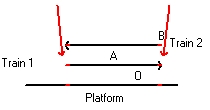
Figure 18 Event (3)
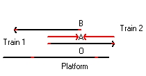
Figure 19
In Figure 16 and Figure 17 the platform and Observer O are at rest. Observer O stays at the center of the two markings.
In Figure 18 and Figure 19 train 1 and Observer A are at rest. Observer A stays at the center of the two markings.
What is important that in both situations all observers see the moments that the light flashes hit the tracks simultaneous. (See Figure 17 and Figure 19). The difference is: who stays at the center of the two markings i.e. respecivily Observer O and Observer A.
In Figure 17 both the train 1 and train 2 seem to move.
In Figure 19 both the platform and train 2 seem to move. Towards the left. - The observer O at the platform is at rest.
Event (1)
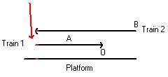
Figure 20 Event (2)
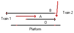
Figure 21 Event (3)
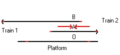
Figure 22
In Figure 20, Figure 21 and Figure 22 this is the same. The difference is that Observer A stays at the center of the two markings. What the three figures indicate, if that is the case, because the train A moves towards the right that the left flash has to hit the track before the right flash hit the track.
- Figure 20 depicts the moment when the left flash hits the back of Train 1. At that same moment it also hits the platform (at rest) and train 2 (The front)
- Figure 21 depicts the moment when the second flash hits the front of the Train 1. At that same moment it also hits the platform (at rest) and train 2 (the back).
It is important to study that in the time difference between Figure 20 and Figure 21 the back of Train 1 has moved a certain distance towards the right. The light flash of event(1) twice that distance. The reason is because the speed of light is twice the speed of Train 1. The position of that flash is above the letters "tf" - Figure 22 depicts the moment when Observer A sees event (1) and event (2) simultaneous.
Also here it is important to see that the distance of both light flashes is twice the distance that Train 1 (also train 2) has moved.
7. Train experiment from the perspectif of obsever A. Moving train
In Paragraph 6 the Observer O at the platform is standing between the two points of contactIn this Paragreph Observer A on the moving train is standing between the two points of contact.
In this case there are two posibilities:
8. Experiment to demonstrate if a system is at rest
-
The purpose of this experiment is to establish if a flat object is at rest or has a certain speed v.
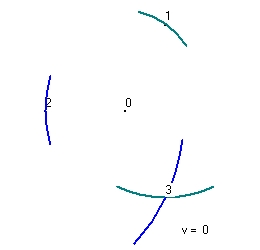
To perform the experiment we use a triangle. The corners are identified as "1", "2" and "3". At each corner there is an observer. The center of the triangle is identified as point "0".
- Figure 23 shows the experiment with v=0.
We have a center at point "0". The center emits a light pulse in all directions at t0. This pulse is received by all three observers at t1. In Figure 23 this is only indicated for observer 1 as event "1" and for observer Observer 2 as event "2". The green circle indicates the pulse received near observer 1. The blue circle indicates the pulse received near observer 2
When Observer 1 receives the pulse at t1 he transmits a green pulse in all directions. Observer 3 sees this flash as event "3" at t2. The green circle indicates the pulse received near observer 3
When Observer 2 receives the pulse at t1 he transmits a blue pulse in all directions. Observer 3 sees this flash as event "3" at t2'. The blue circle indicates the pulse received near observer 3
What Figure 23 shows that two signals are received simultaneous and that t2 and t2' are the same.
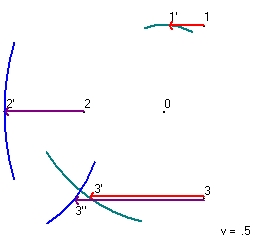
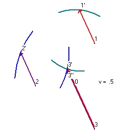
The distance between event "0" and event "1" is 100. The distance between event "1" and event "3" is 173,205. The total distance is 273,205 - Figure 24 shows the same experiment as figure 23 but now the whole triangle has a speed of v=0.5 towards the left.
The center emits a light pulse in all directions. Observer 1 observes this pulse at t1 as event "1'". The reason is because Observer 1 moves towards the left. At event "1'" Observer 1 emits a light pulse in all directions. Observer 3 sees at t2 this light pulse as event "3'".
The distance between event "0" and event "1'" is 86.851. The distance between event "1'" and event "3'" is 200. The total distance is 286,851
Observer 2 observes this pulse at t1 as event "2'". The reason is because Observer 2 moves towards the left. At event "2'" Observer 2 emits a light pulse in all directions. Observer 3 sees at t2 this light pulse as event "3''".
The distance between event "0" and event "2'" is 200. The distance between event "2'" and event "3''" is 123,606. The total distance is 323,606 - The coordinates of the origin is the point x0,y0 = 0,0
- The distance of the origin (r) of the three points is 100.
With an initial angle of 60 degrees the coordinates of the point x1,y1 are 50, 86.602
The distance is 100 and c= 1. With these values t1 = 100/c = 100. See line 1 of results. - The speed of v=0.5 and with phi= 180 you get vx= -0.5 and vy=0.
The new approximation of x1new = x1 + vx*t. The new approximation of y1new = y1 + vy*t
Because the origin is the point 0,0 the "new distance" = sqr(x1new^2 + y1new^2)
Line 2 shows the results x1new = 50 - 0.5 * 100 = 0. Because x1=0, t1=y1/1 - line 3 shows the next results.
x1 becomes larger than zero because t1 is less than 100. - After 12 alliterations the time and distance does not change any more, so that is the final value.
The experiment starts with a light pulse emitted at the origin "0". When an observer detects this light signal he or she also emits a light pulse in all directions. That means each observer should also detect two of these secondary light pulses
The system is at rest when both secondary light pulse are received simultaneous.
 |
 |
 |
A much more basic question is how do you perform with v=0 in reality. In principle you can perform this experiment on the surface of the earth, In reality this is difficult because of the fact that the earth is not flat. That means that point "0" has to be on the top of a mountain.
A different problem is how do you know that your speed = 0. i.e. at rest. See also: Reflection 5 - Usenet discusion: The behaviour of a clock in a linear accelerator versus a centrifuge
|
|
Program description
                x1                     y1                  t1                      angle
calc1 1   x  50                y  86,6025403784439  t  100               arc  60,0000000000151
calc1 2   x  0                 y  86,6025403784835  t  86,6025403784835  arc  90,0000000000227
calc1 3   x  6,69872981075824  y  86,6025403784782  t  86,8612282959635  arc  85,5769631057609
calc1 4   x  6,56938585201825  y  86,6025403784783  t  86,8513490423647  arc  85,6620371419487
calc1 5   x  6,57432547881765  y  86,6025403784783  t  86,8517228125464  arc  85,658787822603
calc1 6   x  6,57413859372679  y  86,6025403784783  t  86,851708666298   arc  85,6589107563491
calc1 7   x  6,57414566685102  y  86,6025403784783  t  86,8517092016901  arc  85,6589061036195
calc1 8   x  6,57414539915494  y  86,6025403784783  t  86,8517091814271  arc  85,658906279711
calc1 9   x  6,57414540928643  y  86,6025403784783  t  86,851709182194   arc  85,6589062730465
calc1 10  x  6,57414540890298  y  86,6025403784783  t  86,851709182165   arc  85,6589062732987
calc1 11  x  6,5741454089175   y  86,6025403784783  t  86,8517091821661  arc  85,6589062732891
calc1 12  x  6,57414540891695  y  86,6025403784783  t  86,8517091821661  arc  85,6589062732895
|
Reflection 1 Train experiment - Technical evaluation
-
Figure 15 - Expected results of an actual experiment.
Starting point is that all three observers see the event (3) simultaneous.- Consider that the length of the platform is 600m and observer O stands in the middle
- Consider that the lightning strikes exactly at the beginning and end of the platform
- The speed of light is 300000 km/sec or 3*10^8 m sec.
- The time it takes for light flash to travel the the point of contact to the observer O of 300m is 300/3*10^8 = 10^-6 second.
- Let us assume that the speed of the train is 108km/hour = 108000/3600 m/sec = 30m/sec= 30000mm/sec
- The distance of the train travelled in 10^-6 second = 10^-6*30000mm = 0,03mm
- That means that in Figure 17, train A, observer A and the two points of contacts have move towards the right the distance of 0,03 mm (compared to Figure 16). This implies that observer A does not stand in the middle.
- Train B and Observer B have moved towards the left and his final conclusion is the same.
- Consider that the length of the platform is 600m and observer O stands in the middle
-
Figure 16 and Figure 17 - Results from Observer O at rest
Now consider Figure 16 with v=0.5
Consider the lightning at right from observer O at t=0. This lightning at impact causes a flash. The distance from the flash d.
Observer O will see this flash t0 later. t0= d/c.
During that time the front, the back and the center of the train 1 will have moved a distance t0*v towards the right. This is depicted in Figure 17.
That means the center between the two points of contact at train 1 (between the front and the back of train 1) will not coincide with the position of observer O.
That means observer A, which is at the same position as observer O, when both see the two flashes simultaneous, can not stand half way between the two points of contact at the train 1.Take a real example.
Consider that the length of the train = 120. That means d = 60. The speed of the train is v=0.5*c . c=1
Observer O will see the flash at tO later. tO=60/c = 60 seconds. During that time the front, the back and the center of the train 1 will have moved a distance tO*v forward = 30
That means observer A will stay a distance 30 from the center of train 1 -
Figure 18 and Figure 19 - Results from Observer A at rest
Let us again study what happens if three observers see event (3) simultaneous, but now in a slightly different setting.- Consider that the length of train 1 is l. Half the distance is d and observer A stands in the middle
- Consider that the lightning strikes exactly at the beginning and end of train A. This is depicted in Figure 18
- In Figure 18, from the point of view of observer A both the platform and observer B move towards the left. Observer A is considered at rest.
Observer A will see this flash t0 later. t0= d/c. During that time the front, the back and the center of the platform will have moved a distance t0*v towards the left.
That means the center between the two points of contact at the platform will not coincide with the position of observer A.
That means observer O, which is at the same position as observer A, when both see the two flashes simultaneous, can not stand half way between the two points of contact at the platform.Take a real example.
Consider that the length of the train = 120. That means d = 60. The speed of the train is v=0.5*c . c=1
Observer A will see the flash at tO later. tO=60/c = 60 seconds. During that time the front, the back and the center of the platform will have moved a distance tO*v forward = 30
That means observer O will stay a distance 30 from the center
That means observer B (which travels from the point of view of observer B with a speed of c towards the left) will stay a distance 60 from the center, or at the back of the train. - Consider that the length of train 1 is l. Half the distance is d and observer A stands in the middle
-
Figure 20, Figure 21 and Figure 22 - Results from Observer A with Observer O at rest
Consider the same situation that observer A stands at the center of train 1, but the platform is at rest. Consider observer A which stands at the center of a moving train with a speed v towards the right. The length of the train is l. The distance from the center is d that means 2*d = l
At t=-t1 lightning strikes the track towards the left of from A. This lightning causes a light flash. The observer sees this flash at t = 0.
A moves away from this flash. That means c * t1 = d + v * t1. or t1 = d/(c-v)
At t=-t2 lightning strikes the track towards the right of from A. This lightning causes a light flash. The observer sees this flash at t = 0.
A moves towards this flash. That means c * t2 + v * t2 = d or t2 = d/(c+v)
The issue is that Observer A sees both flashes simultaneous, but lightning strikes not simultaneous.Take a real example.
Consider that the length of the train = 120. That means d = 60. The speed of the train is v=0.5*c . c=1/second
That means observer A will see the left flash t1 later = 60/(c-0.5c) = 60/(1-0.5) = 120seconds
During that time trian A will have moved a distance v*t1 = 60
That also means observer A will see the right flash t2 later = 60/(c+0.5c) = 60/(1+0.5) = 40seconds During that time trian A will have moved a distance v*t2 = 20
Figure 20 depicts the situation 120 seconds before Figure 22.
Figure 21 depicts the situation 40 seconds before Figure 22.
The time difference between Figure 20 and Figure 21 is 80 seconds. That is why the lightflash in Figure 21 is twice the size of the lightflash in Figure 22.
Reflection 2 - What does an observer near the center of the clock see?
-
What an observer near the center of the clock sees, can observe, is only what happens at the position of his or her eyes. An observer cannot see anything directly what happened far away. He or she observes delayed. This delay depents about the distance involved.
This means that an observer at the center of a clock, only can observe the events when the flashes reach the center, but not before or not there after.
The eye of an observer is infact a sphere with detectors. Assuming that each flash starts with the emission of a fixed number of photons, than IMO the detection eye can measure the magtitude of the receiving number of photons and calculate the distance of the flash. That is almost all.
For an observer at a train this is almost the same. The observer will see the moment when a light flash, which is caused by the impact of lightning a distance away, reaches his eyes. The observer will not see directly the moment when lightning hits the track.
Now consider the situation when the observer sees two flashes simulataneous. Both flashes are caused by lightning. The issue is that the observer can not decide which comes first or if they are simultaneous. Also when the distances are the same this cannot be decided. This is what is explained in Figure 22.
Reflection 3 - The physics of a clock
-
Consider a triangle. The left corner is point A. The right corner is point B. The top is point C. The sides of the the triangle (A-B) (A-C) and (B-C) have all the same length: l.
- Consider an object A which moves from A to B with a speed vA.
- Consider an second object B which moves from A to C to B with a speed vB.
- and assume that both start and arrive simultaneous.
- than it easy to conclude that the speed vA is half the speed vB. When vB=1 than vA=1/2
With c = 1 and v=0 the total travel time t0 = 80.
With c = 1 and v=0.5*c the total travel time of the moving clock using SR (Lorentz transformation) t1 = t0/sqr(1-v^2/c^2) = t0/sqr(3/4) = 80 * 1.154 = 92,376
This is in agreement with simultions. See Technical Data - Figure 2
I call this simulation Lorentz compatable, because it is in agrement with the Lorentz transformation.
For the clock used in the simulation with perpendicular mirrors and with v= 0 the total pathway of one cycle is 80.
With c = 1 and v=0 the total travel time t0 = 80.
With c = 1 and v=0.5*c the total travel time of the moving clock is
t1 = t0/(1-v^2/c^2) = t0/(3/4) = 80 * 1.333 = 106,666
This is in agreement with simultions. See Technical Data - Figure 1
I call this simulation non Lorentz compatible.
In fact all the simulations with perpendicular mirrors are non Lorentz compatible.
It should be mentioned that there is nothing 'wrong' with either clock, both behave differently.
Reflection 3a - Physics - Acceleration
-
A very interesting simulation is figure 4. See Technical Data - Figure 4 This simulation tries to show the behaviour of a clock which speed constantly increases. In fact it shows the behaviour in increments of 0.2*c i.e. at 0.1*c, 0.3*c 0.5*c and 0.7*c. The idea is that there after the speed stays constant.
- In the frame of the accelerator. This frame is at rest and the speed of the clock is increasing.
- In the frame of the clock. In that case (the frame of) the accelerator in total is moving.
It should be remembered that this is a mathematical simulation. The question is if this experiment physical can be performed.
In fact there are two ways to consider this experiment:
Whatever the outcome when you place the clock in a centrifuge the whole physical situation becomes more complex.
Reflection 4 - Overall evaluation
-
The purpose of this paper is to discus the behaviour of clocks, specific the behaviour of a clock as described in the book "SpaceTime Physics" i.e. based on lightflashes.
- What can be observed in principle is that all the observers see the light flashes simultaneous. The light flashes are the results when lightning hits track (or train or platform). This causes finally two markings on the platform and each of the two trains.
- What also can be observed (calculated) if any observer stands in the middle of the markings. This can only be one observer.
- What also can be observed is the relative speed between each object involved (the platform and both trains) in km/hour.
- What cannot be observed is the speed of each object as a function of the speed of light.
For example: it can not be measured (or observed) in a real experiment, as is assumed in the simulation, that an object has a speed of 50% of the speed of light. - The consequence is than when observer A stands in the middle of the two markings that the two events (1) and (2) are not simultaneous. This is depicted in Figure 22.
- However this raises a conflict with the situation described in Figure 19 which assumes that observer A is at rest and that the two events (1) and (2) are simultaneous.
What I try to demonstrate is that this behaviour is very complex when accelerations are involved. The true question is if such a clock can be used for timekeeping.
This same subject is also discussed in Chapter 6 Accelerated Observers in the book Gravitation?
See also: Comments about the book "GRAVITATION" by MTW
However a much bigger issue is at stake and that is depicted in Figure 22.
This solves the issue as depicted in Figure 17 for Observer O.
However it raises an issue for observer A at train 1.
Wath is the correct situation? Or is the full physical situation more complex?
See also the final part of the 1. Introduction
Reflection 5 - Usenet discusion: The behaviour of a clock in a linear accelerator versus a centrifuge
-
The Usenet Sci.Physics.Research (moderated) newsgroup
To read a copy of this discussion select: The behaviour of a clock in a linear accelerator versus a centrifuge
The purpose of the discussion is the behaviour of clocks in a linear accelerator and centrifuge.
This behaviour is simulated in two programmes: "Clock Research.xls" and "VB draw Clock.bas". The two visual basic programmes are identical, except that the platform is different.
- Single object physical laws describe the physical processes primarily related to a single object i.e the earth or the sun or a black hole. That does not mean that not more objects can be considered, like a clock in a train, but they are always fixed connected to the primary object.
- Multiple objects physical laws describe different objects which are not connected which each other and which can move freely through space. For example the planets in our solar system or a satellite in orbid around our earth.
In the simulation a fixed clock is used. The clock does not contain movable parts. The operation of the clock uses light flashes or light pulses. What the simulation shows is that such a clock not always performs correct i.e. the light pulse does not stay in the clock. A different problem is that the simulated clock not always performs as SR predicts. The clock works as SR predicts in a linear accelerator, but not in a centrifuge.
One respondent answers that the clock should have adjustable mirrors. But how this mechanically should be done is not mentioned. As such the whole simulation is wrong. That is correct. But the critique is wrong.
His opinion is also that this is a thought experiment. It is not. The purpose of the simulation should be the reality. That means the behaviour of the model or process its simulate should be the same of the model or proces in real.
A more different issue is if the behaviour of the clock is a problem of SR or GR.
This requires an answer on the question: what is considered SR versus GR.
IMO SR should be related to electro-magnetic processes specific all mechanical processes that require in order to operate electro-magnetic phenomena. Specific all electrical devices and light
GR should be related to mechanical processes based on internal forces and the movement of objects based on external forces i.e. gravity. The same processes can also be studied by Newton's law
What that means SR and GR have nothing physical in common. That does not mean that certain processes can not require both.
The behaviour of a clock, with operation depent on light signals, belongs to SR. That does not mean that all clocks belong to SR. Pendulum clocks (including hourglasses) belong to GR.
SR uses (supports) the concept relativity of simultanity. It does not support (rejects) the concept simultaneous. That is a pitty, because the concept that a set of events "A" can be simultaneous and that a different event "B" can be not simultaneous with the set of events "A" is of physical significance. A set of events "A" is simultaneous means that each of these events is neither caused nor influences any of the other events.
When event "B" is not simulataneous with the set of events "A" this means that event "B" can influence the events "A" or can be influenced by the events "A". In other words the event "B" comes before or after the events "A".
The problem is how do we decide that this is the case. See: 8. Experiment to demonstrate if a system is at rest
In the experiment to cases are simulated: One case with speed is v=0. The second case with v=0.5*c.
The simulations are mathematical correct. The problem is how do you perform them in real. In fact both speeds are a problem. How do you know that your speed = 0 (trully at rest) and how do you know that your speed is half the speed of light.
A much more practical question is: How important is the issue? What is important is to define one rest frame. This can be the centrum of our galaxy or the cosmic microwave background radiation.
Under construction
Appendix 1 - Technical Data
-
Technical Description of the parameters.
- # Segment number. Each cycle normally consits 3 segments and is one tick of a clock
- x0 and y0. This is the position of the flash.
- phiflash. This is the angle of the flash.
- vcl. This is the speed of the clock times c. Intially the direction is clock wise, towards the right.
- vxflash and vyflash. This is the direction of the flash in x,y coordinates
- mirror. The mirror numbers are: 1 bottom, 2 = right, 3 = top, 4= left, 5= horizontal trough the center, 6 = vertical through the center.
- phimirror. The angle of the mirror
- tc . The time of each line segment. One cylcle consits of three line segments.
- tc total . The accumulated time of all line segments.
- xcl0 and ycl0 . The position of the clock.
- r . The distance of the flash from the center of the clock.
- count1 . The number of iterations required to calculate the angle of the flash at the beginning of the cylcle.
This number is 1 for a Long simulation. - count2 . The number of iterations required to calculate the length of each line segment, from the beginning to the point of collision or when it reaches the center.
-
Linear Accelerator - Perpendicular clock - Figure 1 v=0.5
# x0 y0 phiflash vcl vxflash vyflash mirror phi mirror tc tc total xcl0 ycl0 r count1 count2 0 0 0 180 .5 -1 0 4 90 0 0 0 0 0 1 0 1 -13.334 -.001 180 .5 -1 -.001 4 90 13.333 13.333 6.666 0 20 32 154 2 66.666 -.001 359.999 .5 .999 -.001 2 269.999 80 93.333 46.666 0 20 32 825 3 53.333 -.001 180 .5 -1 -.001 6 269.999 13.333 106.666 53.333 0 0 32 155 -
Linear Accelerator - Parallel clock - Figure 2 v=0.5
# x0 y0 phiflash vcl vxflash vyflash mirror phi mirror tc tc total xcl0 ycl0 r count1 count2 0 0 0 90 .5 0 1 3 0 0 0 0 0 0 1 0 1 11.547 20 59.999 .5 .5 .866 3 0 23.094 23.094 11.547 0 20 60 256 2 34.641 -20.001 300 .5 .5 -.867 1 180 46.188 69.282 34.641 0 20 60 485 3 46.188 0 59.999 .5 .5 .866 5 180 23.094 92.376 46.188 0 0 60 256 4 57.735 19.999 59.999 .5 .5 .866 3 0 23.094 115.47 57.735 0 19.999 32 255 5 80.829 -20.001 300 .5 .5 -.867 1 180 46.188 161.658 80.829 0 20 32 485 6 92.376 0 59.999 .5 .5 .866 5 180 23.094 184.752 92.376 0 0 32 258 7 103.923 20 59.999 .5 .5 .866 3 0 23.094 207.846 103.923 0 20 32 257 8 127.017 -20.001 300 .5 .5 -.867 1 180 46.188 254.034 127.017 0 20 32 486 9 138.564 -.001 59.999 .5 .5 .866 5 180 23.094 277.128 138.564 0 0 32 257 -
Linear Accelerator - Perpendicular clock - Figure 3 v=0.1, 0.3, 0.5 and 0.7
# x0 y0 phiflash vcl vxflash vyflash mirror phi mirror tc tc total xcl0 ycl0 r count1 count2 0 0 0 180 .1 -1 0 4 90 0 0 0 0 0 1 0 1 -18.182 -.001 180 .1 -1 -.001 4 90 18.181 18.181 1.818 0 20 32 208 2 26.262 -.001 359.999 .1 .999 -.001 2 269.999 44.444 62.626 6.262 0 20 32 467 3 8.08 0 180 .1 -1 -.001 6 269.999 18.181 80.808 8.08 0 0 32 208 4 -7.304 0 180 .299 -1 0 4 90 15.384 96.192 12.696 0 19.999 32 178 5 49.839 0 0 .299 1 0 2 269.999 57.142 153.335 29.839 0 19.999 32 596 6 34.454 0 179.999 .299 -1 0 6 269.999 15.384 168.72 34.454 0 0 32 180 7 21.121 0 179.999 .5 -1 0 4 90 13.333 182.053 41.121 0 20 32 154 8 101.121 0 0 .5 .999 0 2 269.999 80 262.053 81.121 0 20 32 825 9 87.787 0 179.999 .5 -1 0 6 269.999 13.333 275.386 87.787 0 0 32 155 10 76.023 0 179.999 .699 -1 0 4 90 11.764 287.151 96.023 0 19.999 32 141 11 209.356 0 0 .699 .999 0 2 269.999 133.333 420.484 189.356 0 19.999 32 1356 12 197.591 0 179.999 .699 -1 0 6 269.999 11.764 432.249 197.591 0 0 32 141 -
Linear Accelerator - Parallel clock - Figure 4 v=0.1, 0.3, 0.5 and 0.7
# x0 y0 phiflash vcl vxflash vyflash mirror phi mirror tc tc total xcl0 ycl0 r count1 count2 0 0 0 90 .1 0 1 3 0 0 0 0 0 0 1 0 1 2.01 20 84.26 .1 .099 .994 3 0 20.1 20.1 2.01 0 20 36 226 2 6.03 -20 275.739 .1 .099 -.995 1 180 40.201 60.302 6.03 0 19.999 36 427 3 8.04 0 84.26 .1 .099 .994 5 180 20.1 80.403 8.04 0 0 36 225 4 14.329 20 72.542 .299 .299 .953 3 0 20.965 101.368 14.33 0 20 42 232 5 26.909 -20 287.457 .299 .299 -.954 1 180 41.931 143.3 26.909 0 19.999 42 441 6 33.199 0 72.542 .299 .299 .953 5 180 20.965 164.265 33.199 0 0 42 233 7 44.746 19.999 60 .5 .499 .866 3 0 23.094 187.359 44.746 0 19.999 43 255 8 67.84 -20 299.999 .5 .499 -.867 1 180 46.187 233.547 67.84 0 19.999 43 488 9 79.387 0 60 .5 .499 .866 5 180 23.093 256.641 79.387 0 0 43 256 10 98.991 19.999 45.572 .699 .7 .714 3 0 28.005 284.647 98.991 0 19.999 43 304 11 138.199 -20.001 314.427 .699 .7 -.715 1 180 56.011 340.658 138.199 0 20 43 583 12 157.803 -.001 45.572 .699 .7 .714 5 180 28.005 368.664 157.802 0 0 43 304 -
Centrifuge - Perpendicular clock - Figure 5 v=0.5
# x0 y0 phiflash vcl vxflash vyflash mirror phi mirror tc tc total xcl0 ycl0 r count1 count2 0 0 0 180 .5 -1 0 4 89.999 0 0 0 0 0 1 0 1 -13.37 0 180 .5 -1 0 4 85.212 13.369 13.369 6.677 -.28 20.048 1 159 2 71.868 -14.38 350.424 .5 .986 -.167 2 234.257 86.442 99.812 46.731 -15.069 25.146 1 886 3 67.325 -5.868 118.09 .5 -.471 .882 3 320.802 9.647 109.459 50.559 -18.003 20.696 1 120 4 51.161 -1.085 163.514 .5 -.959 .283 4 44.766 16.856 126.316 56.798 -23.663 23.271 1 193 5 74.035 -80.764 286.017 .5 .275 -.962 2 195.08 82.897 209.214 77.244 -59.186 21.815 1 854 6 67.256 -53.863 104.143 .5 -.245 .969 4 5.146 27.742 236.956 79.677 -72.825 22.668 1 303 7 62.524 -124.154 266.148 .5 -.068 -.998 2 159.917 70.45 307.407 75.136 -107.47 20.914 1 729 8 78.705 -102.135 53.687 .5 .592 .805 4 330.132 27.325 334.732 69.374 -119.84 20.013 1 297 9 50.827 -166.491 246.578 .5 -.398 -.918 3 215.017 70.135 404.867 45.906 -145.519 21.542 1 725 10 13.89 -168.723 183.456 .5 -.999 -.061 2 111.766 37.003 441.871 29.666 -154.297 21.376 1 393 11 35.207 -150.788 40.076 .5 .765 .643 4 281.79 27.857 469.728 16.347 -158.313 20.306 1 303 12 -1.254 -139.991 163.505 .5 -.959 .283 1 358.173 38.026 507.755 -2.55 -159.96 20.01 1 404 13 -41.502 -149.166 192.841 .5 -.975 -.223 2 73.391 41.279 549.034 -22.867 -156.663 20.086 1 436 14 -22.218 -169.176 313.94 .5 .693 -.721 4 243.44 27.789 576.824 -35.771 -151.558 22.227 1 301 -
Centrifuge - Parallel clock - Figure 6 v=0.5
# x0 y0 phiflash vcl vxflash vyflash mirror phi mirror tc tc total xcl0 ycl0 r count1 count2 0 0 0 45 .5 .707 .707 3 359.999 0 0 0 0 0 1 0 1 18.33 18.33 45 .5 .707 .707 3 350.716 25.923 25.923 12.905 -1.048 20.123 1 283 2 46.457 -38.247 296.433 .5 .445 -.896 1 148.09 63.183 89.106 42.285 -12.089 26.488 1 656 3 52.245 -38.273 359.748 .5 .999 -.005 2 236.018 5.788 94.895 44.714 -13.663 25.735 1 83 4 40.83 -10.423 112.287 .5 -.38 .925 4 45.239 30.098 124.993 56.331 -23.196 20.084 1 325 5 85.854 -28.438 338.191 .5 .928 -.372 3 297.874 48.493 173.487 70.718 -42.598 20.726 1 510 6 70.868 -96.351 257.556 .5 -.216 -.977 2 182.969 69.546 243.033 79.892 -75.855 22.393 1 720 7 61.857 -69.235 108.383 .5 -.316 .948 1 82.737 28.574 271.607 79.358 -90.114 27.243 1 311 8 62.494 -68.25 57.091 .5 .543 .839 4 352.317 1.173 272.781 79.281 -90.695 28.028 1 35 9 83.572 -134.925 287.543 .5 .301 -.954 3 237.276 69.927 342.708 67.303 -123.247 20.026 1 722 10 17.771 -143.016 187.009 .5 -.993 -.123 2 123.535 66.296 409.005 44.196 -146.684 26.678 1 688 11 20.976 -137.451 60.061 .5 .499 .866 1 31.236 6.421 415.427 41.485 -148.403 23.25 1 89 12 45.128 -136.434 2.41 .5 .999 .042 4 292.579 24.173 439.6 30.717 -153.868 22.618 1 265 -
Centrifuge - Parallel clock - # Cycles = 1 - Bottom First - Figure 7
# x0 y0 phiflash vcl vxflash vyflash mirror phi mirror tc tc total xcl0 ycl0 r count1 count2 0 0 0 270 .5 -.001 -1 1 146.98 0 0 0 0 0 1 0 1 11.82 -21.109 299.248 .5 .488 -.873 1 171.336 24.193 24.193 12.05 -.913 20.197 58 266 2 44.345 9.674 43.424 .5 .726 .687 3 335.3 44.781 68.974 33.429 -7.32 20.197 58 470 3 43.241 -12.694 267.176 .5 -.05 -.999 5 147.28 22.394 91.369 43.242 -12.694 0 58 248 -
Centrifuge - Parallel clock - # Cycles = 1 - Top First - Figure 8
# x0 y0 phiflash vcl vxflash vyflash mirror phi mirror tc tc total xcl0 ycl0 r count1 count2 0 0 0 90 .5 0 1 3 359.999 0 0 0 0 0 1 0 1 11.162 19.414 60.104 .5 .498 .866 3 351.98 22.395 22.395 11.16 -.783 20.197 60 247 2 21.886 -24.064 283.856 .5 .239 -.971 1 155.944 44.781 67.176 32.61 -6.949 20.197 60 471 3 43.241 -12.694 28.031 .5 .882 .469 5 147.28 24.193 91.369 43.242 -12.694 0 60 266 -
Centrifuge - Perpendicular clock - # Cycles = 1 - Right first - Figure 9
# x0 y0 phiflash vcl vxflash vyflash mirror phi mirror tc tc total xcl0 ycl0 r count1 count2 0 0 0 0 .5 1 0 2 269.999 0 0 0 0 0 1 0 1 39.311 -6.601 -9.531 .5 .986 -.166 2 255.725 39.862 39.862 19.725 -2.47 20.017 40 423 2 14.263 2.033 160.981 .5 -.946 .325 4 66.237 26.494 66.356 32.235 -6.782 20.017 40 290 3 49.293 -16.991 331.494 .5 .878 -.478 6 231.963 39.861 106.218 49.293 -16.991 0 40 422 -
Centrifuge - Perpendicular clock - # Cycles = 1 - Left first - Figure 10
# x0 y0 phiflash vcl vxflash vyflash mirror phi mirror tc tc total xcl0 ycl0 r count1 count2 0 0 0 180 .5 -1 0 4 89.999 0 0 0 0 0 1 0 1 -13.435 -1.985 188.401 .5 -.99 -.147 4 85.136 13.58 13.58 6.781 -.288 20.287 37 161 2 56.97 -25.034 341.872 .5 .95 -.312 2 238.608 74.081 87.662 41.67 -11.71 20.287 37 764 3 47.31 -15.489 135.344 .5 -.712 .702 6 233.745 13.58 101.242 47.31 -15.489 0 37 161 -
Centrifuge - Parallel clock - # Cycles = 1 - Bottom First - Figure 11
# x0 y0 phiflash vcl vxflash vyflash mirror phi mirror tc tc total xcl0 ycl0 r count1 count2 0 0 0 270 .5 -.001 -1 1 178.68 0 0 0 0 0 1 0 1 11.566 -20.034 299.999 .5 .499 -.867 1 179.668 23.132 23.132 11.566 -.034 20 60 253 2 35.119 19.694 59.337 .5 .509 .86 3 359.007 46.185 69.318 34.657 -.301 20 60 485 3 46.183 -.534 298.676 .5 .479 -.878 5 178.676 23.055 92.374 46.183 -.534 0 60 256 -
Centrifuge - Parallel clock - # Cycles = 1 - Top first - Figure 12
# x0 y0 phiflash vcl vxflash vyflash mirror phi mirror tc tc total xcl0 ycl0 r count1 count2 0 0 0 90 .5 0 1 3 359.999 0 0 0 0 0 1 0 1 11.527 19.967 60 .5 .499 .866 3 359.669 23.055 23.055 11.527 -.034 20 60 255 2 34.157 -20.295 299.338 .5 .489 -.872 1 179.008 46.185 69.241 34.618 -.3 20 60 487 3 46.182 -.534 58.677 .5 .519 .854 5 178.676 23.132 92.374 46.183 -.534 0 60 254 -
Centrifuge - Perpendicular clock - # Cycles = 1 - Right first - Figure 13
# x0 y0 phiflash vcl vxflash vyflash mirror phi mirror tc tc total xcl0 ycl0 r count1 count2 0 0 0 0 .5 1 0 2 268.676 0 0 0 0 0 1 0 1 39.998 -.267 -.382 .5 .999 -.007 2 269.427 39.999 39.999 19.999 -.1 20 33 424 2 13.334 .088 179.235 .5 -1 .013 4 89.045 26.666 66.666 33.331 -.278 20 33 292 3 53.326 -.711 358.854 .5 .999 -.02 6 268.472 39.999 106.665 53.326 -.712 0 33 425 -
Centrifuge - Perpendicular clock - # Cycles = 1 - Left first - Figure 14
# x0 y0 phiflash vcl vxflash vyflash mirror phi mirror tc tc total xcl0 ycl0 r count1 count2 0 0 0 180 .5 -1 0 4 89.999 0 0 0 0 0 1 0 1 -13.334 -.089 180.381 .5 -1 -.007 4 89.809 13.333 13.333 6.666 -.012 20 33 156 2 66.648 -1.156 359.236 .5 .999 -.014 2 268.663 79.988 93.322 46.657 -.545 20 33 825 3 53.321 -.711 178.09 .5 -1 .033 6 268.472 13.333 106.656 53.321 -.711 0 33 156
Feedback
If you want to give a comment you can use the following form Comment form
Created: 19 August 2018
Updated: 12 March 2019
Go to Part 2 Clock and Centrifuge - part 2
Go Back to Book and Article Review
Back to my home page Index