Comments about "Spacetime Physics" by Edwin F. Taylor and John Archibald Wheeler - First Edition 1965

This document contains comments about the book: "Spacetime Physics" by Edwin F. Taylor and John Archibald Wheeler
To download the book First Edition select: http://www.eftaylor.com/download.html. This url shows all the possibilities. For a review about the second edition select: Book Review Spacetime Physics II In the last paragraph I explain my own opinion.

Contents

Reflection


Chapter 1. Space and Time

Par 1.1 Parable of the Surveyors - page 1

page 2
This story illustrates the naive state of physics before the discovery of special relativity by Einstein etc.
I doubt this. Using both miles and meters to measure distances does not seem handy.
No one thought of using the same unit for both, or what one could learn by squaring and combining space and time coordinates when both were measured in meters.
You cannot measure time in meters directly. To measure time you need a clock.
Only in 1905 did we learn that the time difference between the second event and first or "reference event" really has different values t and t' for observers in different states of motion
The idea that movement influences the behaviour of clocks was already known for a long time, specific related to ship navigation.
page 3
The invariance of the interval - its independence from the choice of the reference frame - forces one to recognize that time cannot be separated from space.
IMO space and time are physical linked concepts and cannot studied separately.
Space and time are part of the single entity, spacetime.
Spacetime, if you want to use that name, is a mathematical concept. A better name is SpaceCtime
The geometry of spacetime is truly four-dimensional.
Yes mathematically. No physical.
page 4
Time can be measured in meters.
When a mirror is mounted at each end of a stick one-half meter long, a flash of light may be bounced back and forth between these two mirrors. Such a device is a clock.
It should be recognized that this is one type of a clock. What is important how this clock is used in relation to motion. The mirrors can be perpendicular to the direction of motion or parallel. See also Reflection 3 - Worldline Perpendicular Mirrors - Twin Paradox
This clock may be said "tick" each time the light flash arrives back at the first mirror.
The problem is that it is not guaranteed that all clocks behave the same.
To do this here he might as well choose a particular reference frame with respect to which the laws of physics have a simple form.
You can only select something if you define the laws of physics in at least two reference frames. When you do that you can select the simplest case.
The problems involved is also discussed in: Reflection 1 - Three inertial frames.
Now, the force of gravity acts on everything near earth.
It is in some way impossible to exclude that.
In order to eliminate this and other complications, we will, in the next section, focus attention on a free falling reference frame near earth.
I would define such a frame: far away from earth.

1.2 The Inertial Reference Frame - page 5

page 8
If such a reference frame is to be a space ship near the earth, it cannot be very large one because widely separated particles within it will be affected by the nonuniform gravitational field of the earth.
Implying it should not be near earth. See also comments about page 4
page 9
A reference frame is said to be inertial in a certain region of space and time when, throughout that region of spacetime, etc, every test particle that is initially at rest remains at rest and every test particle initially in motion contions that motion without change in speed or in direction
IMO Newton's opinion was the same, except he studied objects (bodies) and he did not use the word spacetime.
See Book "Newton's Principia" page 22
In terms of this definition, inertial frames are necessarily always local ones, that is inertial in a limited region of space time.
Newton as far as I know only used one coordinate system in practice i.e. the solar system. IMO to study such a frame seems much more practical.

Par 1.3 The principle of relativity - page 11

page 12
In each of two inertial frames in uniform relative motion, every test particle that is in motion continues that motion without change in speed or in direction, even though the direction and speed of a given particle will not look the same in both frames.
If we look has nothing to do with this. The issue is that measured values in each reference frame are different while from a physical point of view there is no difference assuming that the measuring tools are not influenced by the different speeds of the reference frames.
In spite of the most diligent search no one has ever found any violation of the following principle:
All the laws of physics are the same in every inertial reference frame.
This seems to be a strange observation because an inertial reference frame is always free falling in outer space? page 13
Notice what the principle of relativity does not say.
It does not say that the time between events A and B will appear the same when measured from two different inertial frames.
Why not write: are the same when measured in two different inertial systems?

Par 1.4 The Coordinates of an Event - page 17

Page 18
We assume that every clock in the latticework, whatever its construction, has been calibrated in meters of light-travel time.
All the clocks in the lattice work should be constructed in exactly the same way. This implies calibration.
When assistants at all the clocks in the lattice have followed this procedure (each setting his clock to a time in meters equal to his own distance from the reference clock and starting it when the light flash arrives, the clocks in the lattice are said to be synchronized,
The whole procedure is rather complicated.
What each clock needs is a reset button (activator) en preset button. With the preset button you can preset a clock to a preset time. This is the time in meters equal to his own distance from the reference clock. The reset button is activated when the light flash arrives. At that instant the clock is started with the preset time,
Page 19
There are other possible ways to synchronize clocks. For example, an extra portable clock could be set to the reference clock at the origin and then carried around the lattice in order to set the rest of the clocks, However this procedure involves a moving clock. We will see later that a moving clock runs at a different rate as measured by clocks in the lattice than do clocks that remain at rest in the lattice.
The last sentence should be modified as follow:
We will see later that a moving clock runs at a different rate than do clocks that remain at rest in the lattice.
The issue that depending about the construction, moving clocks can behave differently.
In relativity we often speak about "the observer". Where is this observer? At one place or all over the place.
In reality what you need is one ideal observer everywhere who can act instantaneous.
The clocks reveal the motion of a particle through the lattice.
When you have one ideal observer this ideal observer can observe and monitor all the events and positions of all the particles or objects instantaneous.
Page 20
From the motion of test particles through the latticework of clocks - or rather from the records of coincidences punched out by the recording clocks - we can determine whether the latticework constitutes an inertial reference frame.
See Reflection - The world accordingly to a lattice for more details.
From the motion of these test particles as recorded by his own clocks, an observer in each frame verifies that his frame is inertial.
The truth is in the details.

1.5 Invariance of the Interval - page 22

Page 22
Nevertheless, an analysis of the track of this pulse through spacetime reveals quickly and simply a quantity (the interval) that is associated with the two events and that has the simple value in all inertial reference frames.
But that interval does not describe all the physics behind the experiments involved.
Event A: A spark plug fires. A flash of light flies up to the reflector R in Fig 13. The flash wings down. Event B the flash is recorded
How is this flash recorded?
This was my initial question. After going more deeply in the subject I realized that the measurements are made by using the lattice. In fact in order to understand SR the first step is to understand what the lattice means and how the clocks are synchronized.
The rocket passes by which such timing that it records the spark as taking place also at its origin and at its zero time. etc
The reception of the flash occurs in the rocket frame at the same place as the emission.
See for more details: Reflection 2 - Comparison between Rocket experiment and Twin Paradox
Page 23
Recall that the speed of light is the same in the laboratory frame as in the rocket frame - the preposterous-but-true character of nature!
In nature nothing is preposterous.
The problem is that you have to perform an experiment (or at least describe an experiment) which demonstrates this. The simplest thing is to define it as an postulate.
Photons are physical objects. These objects have a speed. The whole issue what other physical processes can influence these objects i.e. its speed. If there are no processes which can influence photons than the speed is constant. On the other hand gravity could influence photons. If this happens then there is a problem.
Inertial reference frames have nothing to do with this.
Why is this time greater than 2 meters? Because the hypotenuse of a right traingle in Fig 13A is greater than its altitude!
Okay.
There is no escape from the conclusion that the time between emission and reception is not the same in the two reference frames.
What are we doing? We are comparing observations of the same physical process under two different conditions: In a condition with a frame at rest and in a condition with a moving frame.
page 26
Does this mean that the rules of surveying in the Daytime coordinate system are different from those in the Nighttime coordinate system? Evidently not!
Okay
Similarly there is no flaw in the construction or functioning of the laboratory clocks that makes them give longer readings for the time lapse AB.
The word flaw is wrong. A clock functions based on its construction. As such certain clocks are considered more accurate as others. The issue is how to construct the most accurate clocks (and how to test this accuracy). The different issue is how clocks are used. This can also give accuracy issues i.e. wrong readings.
The "discrepancy" between the laboratory clocks and the rocket clock is caused instead by the character of spacetime geometry itself. That is the way the world is built!
No.
This "discrepancy" I expect is based on clock readings i.e. that the laboratory clock and rocket clock show different times, while assuming they show the elapsed times between the same events, they should not. This discrepancy is caused by the internal functioning of the clocks. Spacetime geometry is away to describe this "discrepancy", but not the cause. The cause is physical.

Par 1.6 The Spacetime Diagram; World lines - page 26

Page 33
Consider a particle moving from O to B along the curved world line of Fig 19B. In this example the particle travels along the axis at a changing speed.
The two sentences should be written in refered order:
Consider a particle that travels along the axis at a changing speed. In this example the particle moves from O to B along the curved world line of Fig 19B.
Let the particle emit a flash of light every meter of time as recorded on a clock carried with it
If you want to understand this you have to know how the clock is constructed i.e. how the clock ticks and measures time. Calibration is a different issue.
Page 34
Because the interval is invariant, the proper time between two events will be the same when calculated in any inertial frame, even though the separate space and time coordinates dx and dt will have different values in different reference frames.
The experiment should be as such that both dx and dt are measured in one inertial frames. Performed in a different inertial frame then both dx' and dt' are measured. The result of the experiment should be that the two calculated intervals are the same for each inertial frame.
Page 35
In this way the proportion of time spent in steady motion at high speed becomes greater and greater.
That is correct.
Thus come eventually to the limiting case where the times of acceleration and deceleration are too short even to show up on the scale of the spacetime diagram (world line OQB in Fig 21)
All of that is true in principle. In reality in any actual experiment always accelerations and decelerations are involved.

Par 1.7 Regions of spacetime - page 36

Page 37
Today this union of space and time is called spacetime.
Spacetime is the arena in which stars, atoms and people live and move and have their being.
I still prefer different: Space is the arena in which stars etc live and move in time.
Space is different for different observers.
That is totally correct: Every observer sees space different. But that is the wrong approach. You should study the laws of physics independent from any observer i.e. without observers. The evolution of the universe is 'controlled' by the physical processes that take place inside the 'universe' and not by the observers.
As such I support the idea of a lattice of clocks which allow to observe the total universe simultaneous.
Time is different for different observers.
I fully agree. As such you should not use moving clocks.
Along that same concept, I support the idea of a lattice of clocks which allows to observe the total universe simultaneous.


Reflection - The world accordingly to a lattice

A lattice is a 3D grid built out of rods with the same length. At is cross section points or grid point there is a clock. That means each clock is surrounded by 6 clocks at the same distance l.
Each lattice can also be an inertial reference frame. That means the laboratory frame can be considered as a lattice and so can the rocket frame.
The synchronisation of the clocks in a lattice is discussed in page 18. Synchronisation starts from the concept that the speed of light is in every reference frame is every direction is the same and equal to c. That means when you emit a light flash at a grid point in all directions through the grid, this light flash will reach the 6 nearest grid points simultaneous. When you know the distance and the speed of light than you can calculate how long is takes for a light signal to travel between two adjacent clocks A and B.
Suppose clock A emits a synchronisation flash then you know when B will receive this signal. This allows you to preset clock B to a certain start time, such that when B receives the synchronistation flash, both clocks run synchrone.
You can do the same for all clocks in each inertial reference frame i.e. laboratory frame and rocket frame.

Chapter 1 discusses two frames a laboratory frame and a rocket frame. The rocket frame has a speed v towards the right. My understanding of the lattice is that when at the start of the experiment both lattices are 'the same', that each time when two grid points pair (considering movement in the x direction) all the other grid points also pair. When that is the case the clock readings don't have to be the same. However when the clocks readings in the two frames are 10 and 8 then the clock readings of all the other clock pairs are also 10 and 8.

The problem with two or more reference frames is that you only can compare physical processes within one reference frame. One reference frame means generally speaking one clock. When you consider a second clock you can define a second reference frame and declare the clock at rest in that frame. But that does not make much sense. The best way is to describe and compare its behaviour (both) within the same frame, only than it makes sense to claim that one clock runs slower or faster than the other.


Reflection - The world accordingly to a lattice - laboratory frame

In this section we will discuss how to synchronise a lattice in a laboratory frame or rest frame.
Figure 1 shows the lattice. In the x direction we have the points x1,x2 and x3 etc. Also x-1 etc. In the y direction: y-1, y1, y2 and y3 etc. In the z direction: z-1, z1, z2 and z3 etc.
In the (x,z) plane are drawn the points a11,a21,a31,a12,a22,a32 etc. similar points are also in the plane parallel to the (x,z) plane going through the point y1 etc.
Figure 1
  • The center of the lattice is the (grid) point O. This point also services as a clock 0. X1 is the nearest point. Clock O functions by means of light pulses. There is mirror between point 0 and x1. When the reflection reaches point O the clock 0 counts 1. When there is again a reflection clock 0 counts 2.
  • There are also mirrors half way between all the 6 nearest points: x1,x-1,y1,y-1,z1 and z-1. All these reflections will reach point 0 (clock 0) simultaneous.
  • The initial light flash from point 0 will, beside being reflected also go to point x1 (and all the 6 nearest points). This signal will reset clock x1 to 1 and start the clock, which functions identical as clock 0. Now there are 7 clocks which show a 1.
  • Point x1 will now be used to initialize the 6 nearest clocks to the value 2 and start the clocks, if not already running. The same for the points y1, z1 etc.
  • This will continue untill all the clocks are started. The result is that all the clocks run synchroneous.

Figure 2
The Figure at the left demonstrates clock synchronisation in the laboratory frame or a frame at rest.
  • Synchronisation starts from the clock at O.
    The diamands in vertical direction shows the world lines how this clock ticks.
  • the point x1 shows the first clock towards the right. When the synchronisation signal reaches this clock the initial value is a 1. The vertical diamonds above the clock show the world lines of this clock.
  • For each of the points x2, x-1, x-2 the same reasoning applies.
  • It is important to mention that the synchronisation is exactly the same in the x, the y and the z direction.


Reflection - The world accordingly to a lattice - rocket frame

In this section we will discuss how to synchronise a lattice in a rocket frame or moving frame. Figure 1 shows the lattice exactly at the same moment when the origin of the laboratory frame coincide with the rocket frame. This is also when moment when the initialisation starts (of both frames). However to reset and start the clocks in the rocket frame is much more complex. The problem is that the rocket moves towards the right and frame considered from the point of view of an observer at rest in the rocket towards the left.
     *z2  
     |
     |          
     -
     |       *y2
     |      . 
     *z1   \ 
     |    . 
     |   *y1  
     -  .
     | \ 
     |.         
* |  O--|---*---|---*---     
     |     x1      x2
   \ |    
  *  -    
    Figure 3              
  • Figure 3 shows only the grid points 0,x1,x2,y1,y2,z1 and z2.
    Figure 2 also shows the 6 mirrors surrounding the origin O, This are the mirrors inbetween point O and the 6 nearest points. Also are shown 3 additional mirrors (between the points x1 and x2 etc)
  • The problem is what happens if the rocket moves towards the right.
    For the in the z axis and the y axis the result will be the same because the mirrors are parallel towards the direction of movement.
    For the x axis this will be different because the mirror is perpendicular towards the direction of movement.
    Except if length contraction is involved in the rest frame.
  • To test if there is length you could better think about two long rods with even space markers. You place one rod above the other. The rod at the bottom will be the rod at rest. The one above the moving rod. Near the bottom rod at each marker you place a clock and you synchronise the clocks as explained. When all the clocks are running all the clocks run synchrone and show simultaneous readings. Next you move the top rod (at high speed) and you indicate the markers of the top rod in red onto the bottom rod (at rest) at the same readings of the clocks at rest. When these red spots are at the same distance as the markers on the bottom rod than there is no length contraction involved of the moving rod.

Figure 4
Figure 4 at the left demonstrates clock synchronisation in the rocket frame or a moving frame. This Figure only applies for the x direction..
  • Synchronisation starts from the clock at O.
    The two tilted lines are the worldlines of the two mirrors. The diamond shapes in between shows the world lines how this clock ticks.
  • The point x1 shows the first clock towards the right. Synchronisation starts with the initial value is a 1. The vertical diamonds in between the tilted lines show the world lines of this clock.
  • For each of the points x2, x-1, x-2 the same reasoning applies.
  • It is again important to mention that the synchronisation in the y and the z direction are different.


Reflection 1 - Three Inertial frames

Consider the following experiment:
     r1-->
      A-->

  x       x

      
x   Earth   x                     Sun


  x       x 

   <--B
     r2-->
               Figure 5
Figure 5 shows two objects: The earth and the Sun. The Earth turns clock wise. At the surface of the (Equator) there are two observers: A and B.
There are at least three inertial frames (three lattices with rods and clocks which require synchronization in 3D):
  1. Frame A with observer A at rest.
  2. Frame B with Observer B at rest.
  3. Frame 3 with the Sun at rest. This seems to me the preferred reference frame.
  4. The moving rockets each also compose an inertial rocket frame.
There are two rockets: one in frame A and one in frame B. Both rockets travel in the direction of the Sun. Both rockets have the same speed i.e. v/c in frame A and v/c in frame B
The question is will both rockets reach the sun simultaneous. Figure 1 shows the initial state at the start of the experiment.

This experiment raises certain problems. Gravity is not considered.
It is important to mention that both rockets can travel in a straight line towards the Sun. In that sense the experiment is not real.


Reflection 2 - Comparison between Rocket experiment and Twin type experiment

In 1.5 Invariance of the Interval - page 22 the Rocket experiment is explained.
In this experiment there in flash at A . Is reflected at R and recorded at B. This happened in what is called the Laboratory Frame.
At the same time there is also a rocket which travels from A to B, with only one Observer, with such a speed that the (moving) Observer can see both emission and reflection.

In the Twin type experiments always two clocks are used. That means one clock stays at home and the other one is moved from A to B and back to B. The result is that the moving clock runs slower.
What a clock is, is described in 1.1 Parable of the Surveyors - page 1 See page 4.
The problem is you can have two types of clocks: The difference between the two is that in the rocket experiment you need a lattice of clocks as mentioned at page 18. As such in the rocket experiment there are no moving clocks involved. In the twin experiment there are two clocks involved: one at rest (at A) and one is moving (from A to B).
To compare the two you must also build inside the rocket a clock. That means two horizontal mirrors parallel in the direction of movement.
To start and stop this clock the two events A and B are important. The observer inside the rocket starts the moving clock (This causes a second light flash. Event A') when she sees event A, and she stops the moving clock (Event B') when see sees the reflection of this second light flash. And what see we now as a big surprise: (?) the two events B and B' happen simultaneous.
This experiment tells you that a moving clock runs slower, because event B' is equivalent with the first tick of the moving clock while the clock at rest (this are all the clocks in the lattice, specific the one near event B) already shows a higher number of ticks (i.e. sqrt(1+dx/2)).


Reflection 3 - Worldline Perpendicular Mirrors - Twin Paradox

Figure 6
It is important that this clock works with two parallel mirrors perpendicular in the direction of movement.
In the example at page 22 the mirrors are parallel in the direction of movement.
  • Figure 6 shows one clock A at rest and a moving clock B with a speed v towards the right.
    Each clock uses two mirrors, perpendicular to the direction of movement.
    The two mirrors are identified with the two black lines.
    The clock A shows 8 ticks. The ticks are identified with the numbers from 0 to 8.
    The path of the two lightbeams is drawn in cyan. The moving clock B shows 6 ticks. The ticks are identified with the numbers 0 to 6.
    The path of the two lightbeams is drawn in red.
  • Fig. 19a and 19b at page 33 shows a comparison between the straight line distance along the y axis and the distance along the winding path.
    When you compare the total length of the light path in Figure 6 for each observer, the length is exactly the same.
    The total length dA for observer A is c * nA * t0. With nA equal to the number of ticks and t0 the time of each tick.
    The equation used to describe the case of the moving clock B is: t1 = t0/(1-v^2/c^2)
    see: Reflection 2 - Moving Observer - Figure 8

    With v = 0.5C we get t1 = t0 / (1-1/4) = 4*t0/3
    The total length dB for observer B is c * nB * t1. With nB equal to the number of ticks and t1 the time of each tick.
    Because the total length is the same we get: c * nA * t0 = c * nB * t1 = c * nB * 4*t0/3.
    With nA = 8 we get c * 8 * t0 = c * nB * 4*t0/3. Or 8 = nB*4/3. Or nB = 6

Using the concept that the total light path for each observer is eaxctly the same you get the following equation:
c * nA * t0 = c * nB * t1
With for observer A: nA equal to the number of ticks and t0 the time of each tick and
for observer B: nB equal to the number of ticks and t1 the time of each tick.
with t1 = t0/(1-v^2/c^2) we get: c * nA * t0 = c * nB * t0/(1-v^2/c^2) or nA = nB * /(1-v^2/c^2)
next we get: nB = nA * (1-v^2/c^2) which reflects clock counts of moving clock
next we get: nB = nA - nA * v^2/c^2 or nA * v^2/c^2 = nA - nB
v/c = sqrt( (nA-nB)/nA) or v/c = sqrt(1-nB/nA)
This is a very important equation because it allows you to calculate the speed of a moving object based on the clock counts of both clocks.
With nA = 8 and nB = 6 we get: v/c = sqrt(1-6/8) = sqrt (2/8) = sqrt(1/4) = 0.5
Or v= 0.5 * C

In my humble opinion this equation is more practical than the lorentz transformation because it is purely based on observations.
For further reading select this link: Reflection 3 - Are all moving rods at rest?

Mentioned above: the total length of the light path in Figure 6 for each observer is exactly the same. What that means is that in principle both clocks should show the same time. Because they don't in reality, moving clocks should not be used to measure speeds. Or there time indications should be corrected.


Reflection 4 - Worldline Parallel Mirrors - Rocket experiment

Figure 7
The figure on the left represents the x,y plane of the experiment with two parallel mirrors.
  • The line A-F-B and the line D-R show the parallel mirrors of the moving clock to the right.
  • The points A and B are the events A and B. Event A: A spark plug fires. Event B the flash is recorded.
  • The line A-R and R-B describes the path of the light flash in the Laboratory plane.
  • The line A-D (D-A) describes the Light for a clock at rest.
    The line F-R describe the Light path from the point of view of an observer in the rocket.
  • The total time for light signal in the laboratory frame is 2*t0. In the rocket frame is 2*t1. The equation used to describe the case of the moving clock B is: t1 = t0/sqr(1-v^2/c^2)
    see also: Reflection 2 - Moving Observer

    With v = 0.5C we get t1 = t0 /sqr(1-1/4) = t0/sqr(3/4) = 2*to/sqr(3)
    The total length dB for observer B is c * nB * t1. With nB equal to the number of ticks and t1 the time of each tick.
    The same equation we can also express in clock counts Because the length is the same we get: c * nA * t0 = c * nB * t1 Because t1 = t0/sqr(1-v^2/c^2) we get c * nA * t0 = c * nB * t0/sqr(1-v^2/c^2) or:

    nB = nA * sqr(1-v^2/c^2)
    With nA = 8 and v = 0.5c we get nB = nA * sqr(1 - 1/4) Or nB = 8 * sqr(3/4) Or nB = 4*Sqr(3)
    This result is in agreement with Special Relativity i.e. Lorentz Transformation.

    Using nB = nA * sqr(1-v^2/c^2) we get: nB^2 = nA^2 * (1-v^2/c^2). Next we get nB^2 - nA^2 = - nA^2*v^2/c^2 or v^2/c^2 = (nA^2 - nB^2)/nA^2) Next we get v/c = sqr(1 - nB^2/A^2) This is a very important equation because it allows you to calculate the speed of a moving object based on the clock counts of both clocks.
    With nA = 8 and nB = 4*Sqr(3) we get: v/c = sqr(1-48/64) = sqr(16/64) = sqrt(1/4) = 0.5
    Or v= 0.5 * C

Figure 8
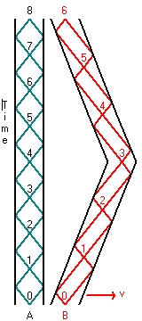
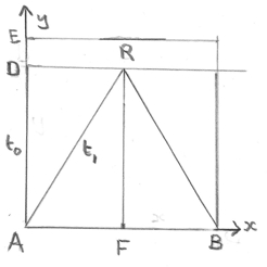
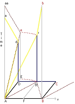
Figure 8 on the left represents the x,y,t spacetime frame of the experiment with two parallel mirrors.
  • The mirror in front contains the points aa, a, A, F, B and b.
  • The mirror in the back contains the points d, D, R, C and r.
4 world lines are displayed.
  • The yellow line A-d-a represents the lightpath of a photon which travels from A to D, is reflected back, against the mirror, to A.
    The same for a photon which travels from F to R and back to R.
    The line represents the world line of rocket at rest.
  • The line A-r (in the plane A,R,r) and the line r-b (in the plane R,B,b,r) together are the worldline of the lightpath of the photon which travels from A to R to B. The line represents the world line of a moving rocket.
  • The line A-e-aa represents the lightpath of a photon which travels from A to E (reflected) and back to A.
    Because the length A-E and A-R are the same, the length of this line also represents the length of the light path going from A to R to B.
  • the line A-b (not shown) in the plane A,B,b represents the worldline of the moving rocket in the laboratory frame.
IMO what you can learn from this exercise that the concept of worldlines in rather complex in 2D. It will be more complex in 3D.
From a physical point of view the most important lesson is that the time t1 is larger than t0, which implies that a moving clock runs slower than a clock at rest.


Reflection 5 - Worldline Parallel Mirrors - Clock synchronisation

Figure 9
The figure on the left shows clock synchronisation in the x and y direction. (ground plane) The movement is towards the right in the x direction.
Figure 9 shows two mirrors.
  • The first mirror is the horizontal line through point R. This is the reflection mirror in the Y direction towards the clocks y1, y2, y3 etc.
  • The second mirror is the vertical line through point A'. This is the reflection mirror in the X direction towards the clocks x1, x2, x3 etc. This mirror moves towards the right.
Point A is the origin of the synchronisation signal
In the rocket experiment the clock signal moves in the ground frame from point A towards point R (is reflected) and returns towards the observer at point B.
In the clock synchronisation experiment this signal is not reflected but continues and reaches clock y1 at point R'' in the ground plane.
in the space time diagram this the point B'.
The line A, R', B', x' shows the world line of the origin.
The line A', X shows the world line of the second mirror.
The line A, D', E' X shows world line of the synchronisation signal in the x direction. This signal reaches the origin at point X'
What Figure 9 clearly shows is that the synchronisation time in the x direction and the y direction are different.
In the y direction this is the horizontal line through the point 2t1 (E'' and B').
In the x direction this is the horizontal line through the point X' (not drawn, which is larger as 2t1.
See in 1.4 The Coordinates of an Event - page 17 for more detail.
IMO the general conclusion is that moving reference frames can not be used to study physics.


Reflection 6 - What is wrong with the book "Space Time Physics" and SR

When you study Newton's Law what is almost missing is the concept of time and a full treatment of clocks i.e. moving clocks. Only the pendulum is discussed (in an excellent way).
When you study the book "Gravitation" at page 393 (See also Book Review GRAVITATION by MTW #page393 you can read that pendulum clocks only is ideal when at rest.
This raises the question what happens when clocks are moved from one place to another. Apparently something, because why mention the above.
Ideal clocks are discussed at page 397. (See also Book Review). Reading these pages IMO nothing is mentioned about the ticking rate whan the clock is moved.

The problem with the book "Spacetime Physics" is that the behaviour of clocks is not directly (separately) discussed in the first chapter.

In chapter 1 the concept of Inertial frames is emphasized. Why?
When you want to understand the laws of nature a global approach is required i.e. one coordinate system. You do not need a second reference frame to fine tune the first. It also does not make sense to declare that the laws of nature are the same in each reference frame. Such a claim does not unravel these laws, add laws or fine tune a law.

When you want to understand the behaviour of clocks you should study them in one coordinate system. That means you should compare the behaviour of two clocks within the same frame. You should make this frame as large as possible and by means of experiments establish which clock runs the fastest.

When you have two clocks (in relatif movement) it is important to consider that the speed of a specific light ray is the same for both clocks (locally). The same for a light ray going in the opposite direction (locally). That does not mean that the speed of a light ray (travelling from the Sun towards the earth) is everywhere the same.


Reflection 7 - Explanation Twin Paradox.

The name "Twin Paradox" is wrong. A much better name is "The moving clock paradox". The paradox (even the word paradox is wrong) has much more to do with the explanation of the physical behaviour that: a moving clock counts at a different rate compared to a clock at rest.
It is important to understand that a clock is nothing more than a physical (mechanical) process, which functioning is a combined colaboration of the internal parts of the clock.
To explain this in more detail: let us start with clock A. This clock A we call at rest.
We also have a second clock B (which is identical as clock A). We put clock B in a spaceship. We send this space ship for 1 year in the direction of the center of the Milky Way and back towards A with a speed of 0.5 times the speed of light c. When the two clocks are united we compare the readings (counts).
Figure 10
Figure 6 (above) and Figure 10 shows the results of this experiment. Clock A has counted 8 ticks and clock B 6 ticks. That means the average count rate is 4 versus 3 per year.
A year being defined as a complete revolution of the Earth around the Sun.
That means the moving clock ticks slower.
The idea behind figure 10 is to do the same experiment again but with a slight modification:
Each time when a clock tick it will also send a signal towards the other clock. The idea is to emphasize the differences between the two clock. It is important to remember that both clocks are the same and each uses two parallel mirrors. The direction of the mirrors are perpendicular to the direction of movement
  • Let us start with Clock A. The most important part of each clock is the center of each clock. The originator. The originator produces the flashing signal and shows the counts. (This should be the position of observer A).
    Clock A operates like an oscillator. The flashes start at the originator, are reflected at the mirrors and when they meet (at the center line of clock A) the clock counts 1. At that moment also a flash is transmitted towards clock B. This flash will cross the center line of clock B when clock B has counted 1.5 counts.
    This same process will repeat when clock A counts 2. This flash will cross the center line of clock B when clock B shows 3 counts.
    At that moment the spaceship will starts it return leg
    When clock A counts 3 clock B will count 3.5. When clock A counts 4 clock B will count 4.
    When clock A counts 5 clock B will count 4.5. When clock A counts 6 clock B will count 5.
    When clock A counts 7 clock B will count 5.5. When clock A counts 8 clock B will count 6.
  • Now we follow Clock B. This clock when it counts 1 will transmit a signal towards clock A.
    When clock B counts 1 clock A will count 2. When clock A counts 2 clock B will count 4.
    When clock B counts 3 clock A will count 6. When clock A counts 4 clock B will count 6.5.
    When clock B counts 5 clock A will count 7. When clock A counts 6 clock B will count 8.
The two most important events are:
  1. When clock A counts 6. This is the moment that clock A receives count 3 of clock B. Between count 6 and count 8 of clock A, clock A will receive 3 counts of clock B.
  2. When clock B counts 3. This is the moment that clock B receives count 2 of clock A. Between count 3 and count 6 of clock B, clock B will receive 6 counts of clock A.
Those two events define a difference in frequency of the receiving signals, which are specific for this type of clock with perpendicular mirrors in the direction of movement.

But now comes the most important exercise of this experiment.

What happens if B is considered (a spaceship) at rest and A is the moving spaceship.
In that case at the start both spaceships start with the speed of spaceship B and the speed of spaceship A is modified.
The important issue is that in that case we still can use the bottom part of Figure 10, because there is no physical difference.
In that case at the red point 3, clock B should not modify his speed but continue for 3 more ticks, to finish his two year travel period (considered at rest).
In fact clock B's total should be 8 ticks to match the previous example (A at rest).
The only conclusion is to consider B at rest creates havoc.

The only conclusion is also that performing an experiment like in figure 6 and figure 10 and if the results are such that at the end of the experiment clock B shows less counts than clock A that clock A has the lowest speed.

You can also do the same experiment when the mirrors are parallel in the direction of movement. Clock A will still count 8 counts, but the count of clock B will be different (when they meet)


Feedback

none


If you want to give a comment you can use the following form Comment form
Created: 22 August 2017
Modified: 2 July 2018
Modified: 1 October 2019

Go Back to Book and Article Review
Back to my home page Index