On the Electrodynamics of moving Bodies - by A. Einstein 1905 - Article review - Appendix 2

This document is Appendix 2 of the 1905 Article Review "On the Electrodynamics of moving Bodies - by A. Einstein 1905 - Article review".
To read the 1905 Article Review select: Article_Review_On The Electrodynamics Of Moving Bodies.htm

Appendix 2 is part of 1905 Article Review section: "Reflection 4 - Conclusion" . To read select: Reflection 4 - Conclusion.

The 1905 Article Review also contains an Appendix 1. In order to read "Reflection 4 - Conclusion - Appendix 1" select: Article_Review_Moving Bodies_Appendix.htm

Contents

Reflection

1. Introduction

The purpose of this document is to explain in more detail the physical implications of experiment 1 and 2 of Appendix 1 of the 1905 Article Review.
Experiment 1 only involves a small part of a complete twin paradox type experiment. Experiment 2 of Appendix 1 is renamed experiment 3.

2. Experiment 1

Experiment 1 starts, assuming we are at rest, assuming that the speed of light is the same in all directions and with a set of equally spaced clocks a distance l apart. All the clocks are identical and there inner working is based on light signals.
  1. The first step of experiment 1 is what is called clock synchronization.
    Clock synchronization starts from a common light source, also called a reset signal.
    Clock synchronization starts from the idea that the light path from the light source towards each clock should be the same.
    • In the case of 2 clocks this distance is 0.5*l. The two clocks are #1 and #2. To synchronize, the light source should be in between the 2 clocks, because the distance between clock #1 and clock #2 is each 0.5*l and the same.
    • In the case of 4 clocks this distance is 1.5 * l. The four clocks are #1,#2,#3 and #4
      The light source is in between points #2 and #3. From there it goes to two new reset points: one reset point in between the points #1 and #2 and one in between the points #3 and #4. Light distance is l.
      The first reset point is used to reset the clocks #1 and #2. The second reset point is used to reset the points #3 and #4. Total light distance is l+0.5l = 1.5l.
    • In the case of 8 clocks this distance is 3.5 * l. The eight clocks are #1 through #8
      The light source is in between the points #4 and #5. From there it goes to two new reset points: one reset point in between the points #2 and #3 and one in between the points #6 and #7. Light distance is 2.
      The first reset point in between the points #2 and #3 is used to create two new reset points: one between the points #1 and #2 and one between the points #3 and #4
      The second reset point in between the points #6 and #7 is used also to create two new reset points: one between the points #5 and #6 and one between the points #7 and #8.
      Each of these 4 reset points is used to reset the two nearby clocks. Total light distance = 2l+1l+0.5l = 3.5l
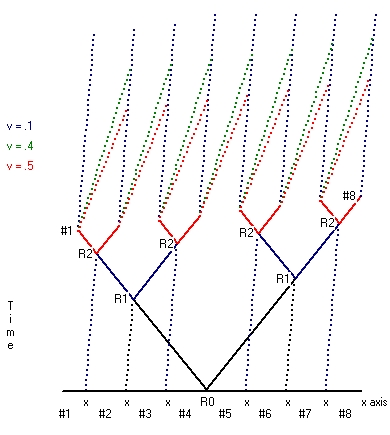
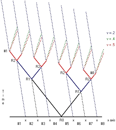
      Physical Space
      Picture 1
      Picture 1 on the left shows Clock synchronization for 8 clocks, identified with the numbers #1 until #8.
      The horizontal axis shows the x-axis.
      The vertical axis shows the time-axis
      • The point R0 contains the reset source (halfway between the clocks #4 and #5) This is the position of the clock tested.
        From this point two reset signals are issued in the +x and -x direction towards the points R1. These signals are drawn under an angle of 45 degrees.
      • The two points R1 are beam splitters. They are in some sense completely identical as R0. From each of these points two reset signals are drawn in the +x and -x direction.
      • The four points R2 are beam splitters. They are in some sense completely identical as R0 and R1. From each of these points two reset signals are drawn in the +x and -x direction towards the 8 clocks.
      • When the reset signals reach the clocks #1 to #8 they are reset. Because the path length is the same, they run simultaneous.
    This same methodology can be used to synchronize any number of clocks.
  2. The second step is what is called: moving clock synchronization
    moving clock synchronization comes in two flavours.
    1. The first type starts from a situation where the reset point is considered at rest. This type is depicted in Picture 1. Picture 1 shows Clock synchronization for 8 clocks along the x-axis. In the case of moving clock synchronization a rod is used which also contains 8 clocks (example) at the same position as each of the 8 clocks along the x-axis. That means when the reset signal is 16 clocks are synchronized at rest. This is the first part.
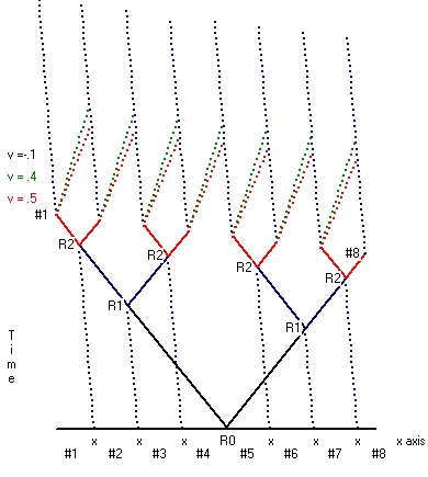
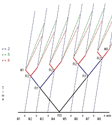
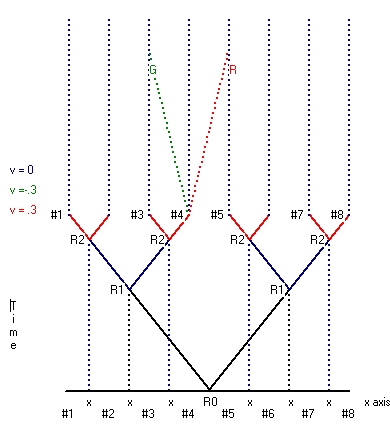
      The second part is that the rod is moved. During this movement all the 8 moving clocks stay synchronized, but the clocks all run synchronic slower. When the movement stops all the 16 clocks tick at the same rate, but the 8 clocks moved run behind versus the 8 clocks which stayed at rest.
    2. The second type starts from the situation where the reset point is not considered at rest. This type is shown in Picture 2 for both v=0.2*c and v=0.4*c.
      Starting point is exactly the same as in Picture 1. Initially there are 8 clocks equal spaced a fixed distance l apart. There is a reset point in between the clocks #4 and #5. The whole setup is considered to move towards the right. The speed of light is again considered to be the same in all directions.
      When this is the case what Picture 2 shows is that clock #1 receives the reset signal physical first, then clock #2, then clock #3 etc. What Picture 2 also shows is that the time difference between clock #2 and clock #1, compared with clock #3 and clock #2 is the same
    Physical Space
    Picture 2
    What Picture 2 shows, that clock synchronization starting from a moving reset point is different compared with the situation that the reset point is at rest i.e. Picture 1
    All the moving clocks tick at the same rate, but the number of counts of each clock, after synchronization will be different. In this case clock #1, which physical starts first, shows the highest count. Clock #8, which physical starts the last, shows the lowest count. The distance between all the clocks is the same and the difference in counts between each clock is the same.

    Now what happens, when the clock is reset, attached to each clock an engine is fired (each in the same direction with a standard boost) to give the rod a certain speed?
    In this particular case the engines at the back are started first. There are two possiblities:

    1. When the direction of the engine is same direction as the speed of the rod, the engines at the back will try to increase the speed of the rod. These forces will try to compress the rod.
    2. When the direction of the engine is in the opposite direction as the speed of the rod, the engines at the back will try to decrease the speed of the rod. These forces will try to enlarge the rod.
    This distance will not change when clock synchronization is performed starting from clocks at rest, as depicted in Picture 1, using the same power boost for each engine, because all these clocks will start simultaneous.
    See for more technical detail "Reflection 4" See also: Reflection 2 - The behaviour of moving clocks.
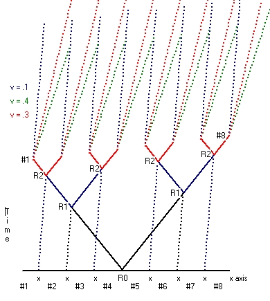
  3. The third step indicates the beginning of the experiment. This means that the engine that moves the rod is turned on.
    At the front end of the rod there is an observer which observes both the readings of the clock at rest and the moving clock when he passes the next clock at rest.
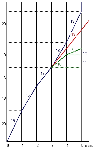
    The following table shows the results when the observer in front passes the clocks #3 to #9
    The clock readings in counts represent the increments between each reading. To get the actual counts observed you have to add these increments.
    clock v0 n0 v1 v^2 c^2 gamma n1 time 0 time 1
    2 0 0 0 100 100/100
    3 0 1000 1 1 100 99/100 990 1000 990
    4 0 500 2 4 100 96/100 480 1500 1470
    5 0 333 3 9 100 91/100 303 1833 1773
    6 0 250 4 16 100 84/100 210 2083 1983
    7 0 200 5 25 100 75/100 150 2283 2133
    8 0 166 6 36 100 64/100 106 2449 2239
    9 0 166 6 36 100 64/100 106 2615 2345
    Table 1
    • Column 1 shows the clock # for the observer in front.
    • Column 2 v0 shows the speed of the rod as measured with the clocks at rest.
    • Column 3 n0 shows the # of counts of the clock at rest. The # of counts is an indication of time passed.
      What the full table shows is that the number of counts (increments) decreases because the speed in creases.
    • Column 4 v1 shows the speed of the rod as measured with the clocks at rest. v1 = 1000/t = 1000/n0. The speed of light c = 10.
    • Column 5 v^2 shows the speed of the rod v1 in the power of two
    • Column 6 c^2 shows the speed of light in the power of two. c^2 = 10^2 = 100
    • Column 7 gamma shows the factor gamma. Gamma is defined as (1-v^2/c^2).
    • Column 8 n1 shows the # of counts of the moving clock. The # of counts of the moving clock is lower than the clocks at rest, which mean that the moving clock runs physical slower; the moving clock runs behind.
    • Column 9 time 0 shows the time (in counts) of the clock at rest. This is the sum of column 2 i.e. n0
    • Column 10 time 1 shows the time (in counts) of the moving clock. This is the sum of column 7 i.e. n1
  4. The fourth step involves the observer at the back of the rod. This observer also observes both the readings of the clock at rest and the moving clock when he passes the next clock at rest.
    The interesting part is that he writes down exactly the same results as the observer in front.
    The reason is physical because the whole rod undergoes the same physical changes and forces at each instant.
    The moving clocks once synchronized, stay synchronized during the whole trip.
    However, the moving clocks are not synchronized with the clocks at rest. The moving clocks run slower.
  5. The fifth step involves the physical situation that the rod undergoes accelerations. That means the rods is during part of this trip in non-linear movement. This is the physical reason why the moving clock runs slower as the clock at rest. Its light path is longer as the clock at rest.
    When the position of the observer in front coincides with the clock at rest #8 the engine, which moves the rod, is turned off.
  6. From there on the rod is in linear movement. The same for the observer at the back with clock #8.
  7. When studying the physical behaviour of the moving rod it is important to notice that it does not matter in which direction the moving rod behaves. This whole experiment is symmetrical.
    The next table shows the situation for the same clock as above, but now moving in opposite direction.
    clock n0 v0 v1 v^2 c^2 gamma n1 time 0 time 1
    2 0 0 0 100 100/100
    1 1000 0 -1 1 100 99/100 990 1000 990
    0 500 0 -2 4 100 96/100 480 1500 1470
    -1 333 0 -3 9 100 91/100 303 1833 1773
    -2 250 0 -4 16 100 84/100 210 2083 1983
    Table 2

3. Experiment 2

Experiment 2 is a continuation of Experiment 1. During Experiment 1 the engine is turned off, but the rod is still moving. These observations are described in the following table.
clock n0 v0 v1 v^2 c^2 gamma n1 time 0 time 1
19 166 0 6 36 100 64/100 106 4275 3405
20 166 0 6 36 100 64/100 106 4441 3511
21 200 0 5 25 100 75/100 150 4641 3661
22 250 0 4 16 100 84/100 210 4891 3871
23 333 0 3 9 100 91/100 303 5224 4174
24 500 0 2 4 100 96/100 480 5724 4650
25 1000 0 1 1 100 99/100 990 6724 5640
25 1000 0 0 0 100 100/100 1000 7724 6640
Table 3

4. Experiment 3

Experiment 1 we start from a system physical at rest. Experiment 2 starts from a moving system i.e. a moving rod. Experiment 3 starts from the same initial state as experiment 2, except that we call the rod at rest.
clock v0 v0 v1 v^2 c^2 gamma n1 time 0 time 1
20 6 6 0 100 100/100
21 6 1000 5 1 100 99/100 1010 1000 1010
22 6 500 4 4 100 96/100 520 1500 1530
23 6 333 3 9 100 91/100 365 1833 1895
24 6 250 2 16 100 84/100 297 2083 2192
25 6 166 1 25 100 75/100 221 2249 2413
26 6 0 36 100 64/100 2249 2413
Table 4

5. Experiment 1, 2 and 3

This paragraph is a discussion of all the 3 experiments, which is shown in the tables 5a,5b and 5c
One important point is that from a physical point of view the three experiments are almost identical, the main difference is in the behaviour of the clock at rest used. This difference is a result of the moment of synchronization.
The moving rod has (at least) two clocks and observers. The moving rod moves in a straight line.
clock v rest moving
1 0 100 100
2 1 100 99
4 2 100 96
7 3 100 91
11 4 100 84
Table 5a
v 'rest' moving
-2 96 100
-1 96 99
0 96 96
1 96 91
2 96 84
Table 5b
v 'rest' moving
-4 84 100
-3 84 99
-2 84 96
-1 84 91
0 84 84
Table 5c
clock v rest moving
1 0 100 100
0 -1 100 99
-2 -2 100 96
-5 -3 100 91
-9 -4 100 84
Table 5d

Reflection 1 - Common understanding

Behind both experiments, there are a certain set of rules or concepts.
  1. First of all the idea is to unravel the rules of physics solely by means of experiments, and to see if this causes any problems.
  2. As part of these experiments only one reference frame used. This is a frame or grid at rest. No moving frame is explicitly used. What is used, is the concept of moving objects, for example, a rod or a clock. The concept of moving objects is discussed in relation to the frame at rest.
  3. What is also mentioned is that the speed of light is the same in all directions for a clock at rest, but again not explicit for a moving clock or rod.
  4. In experiment 1 we start from a situation that all the clocks involved are synchronized at rest. This can a called a global frame at rest.
    In experiment 1 the engine is started and the speed of the rod increases. After a certain period, the engine is stopped and the rod is in linear movement.
    From a physical point, both moving clocks are running slower compared to the clocks at rest.
  5. In experiment 2 the engine is set in the reverse direction. The engine is started. From a physical point of view, the speed decreases and the moving clock starts to run faster (but still slower as the clocks as rest).
  6. Experiment 3 is physical identical as experiment 2, with the only difference that the moving rod is now considered at rest and that all the clocks are synchronized with these clocks. This can be called a local frame at rest.
    When the engine is started the rod starts moving and its speed increases, relative to the clocks at rest. But physical its speed decreases. The moving clock starts to tick faster than the clocks at rest. (in the local rest frame)
  7. That means, that the behaviour of a clock is physical different if it is at rest or moving.
    When at rest and a force is applied the clock will always run slower.
    When moving, depending on the direction of the force, the clock can run faster or slower.
  8. In experiment 1 'you' are moving with increasing speed over a set of equal spaced clocks at rest.
    That means the time 'between' you meet these clocks decreases and your own time decreases. A moving clock runs slower.
  9. In experiment 3 'you' are moving with decreasing speed over a set of equally spaced moving clocks (in the same direction)
    That means the time 'between' you meet these clocks increases and your own time increases. A moving clock runs faster.
  10. Experiment 1 is a typical symmetrical experiment. Experiment 3 is a typical asymmetrical experiment.
    The most probably result, if you perform the experiment in general, without knowing if the rod is physically moving or at rest, is the type 3 (asymmetrical) experiment.
  11. The bottom line is that experiments performed with clocks will have different results, depending on the initial physical speed of the rod. This initial speed defines the physical speed of all the clocks used in the rest frame and indirectly the measurements observed.

Reflection 2 - The behaviour of moving clocks.

At the beginning of Experiment 1, clock synchronization is discussed using clocks at rest, (in a frame at rest).
Clock synchronization is based on the concept that all the clocks are in one straight line, at equally spaced distances l.
The idea behind clock synchronization is that one clock is called a reset clock. The reset clock issues a reset signal, which is used to reset all the clocks to be synchronized, assuming that the path length (using reflecting mirrors) to all the clocks is the same. The result is, that the reset signal reaches all the clocks simultaneous.

This same signal can also be used to reset the two clocks at the front end and back end of a rod, which has the distance l and which position coincides with two clocks at rest.
In order to observe the behaviour of moving clocks, perform the following experiment:

What this means is that moving a clock changes the behaviour of a clock (based on light signals). This is a temporary effect
The question is, is this in conflict with the first law of relativity, which reads:
The laws by which the states of physical systems undergo change are not affected, whether these changes of state be referred to the one or the other of two systems of co-ordinates in uniform translatory motion.
The problem with this sentence or postulate is what is meant with the word laws. Laws are descriptions in mathematical notation. The issue is here that we try to unravel these laws by means of experiments and it does not make sense to put constraints on these laws before the results of the experiments are properly described and investigated.
A different issue is that in any experiment that involves movements always accelerations are involved
See also
"Article_Review_On The Electrodynamics Of Moving Bodies" page 4 by Albert Einstein.

Reflection 3 - Are all moving rods at rest?

The most important lesson is when you are on board a moving rod at almost any instant you can observe that you are on a moving rod because your clock runs slower than the clocks at rest. This can also be almost instantaneous depending on what the distances are between the clocks at rest .
However the same is true if you are at rest and when a rod passes you. Also, this can be instantaneous depending on the number of clocks on the moving rod and the distance between these clocks.
You can even place a continuous number of synchronized clocks near what you can call a moving frame

The following picture indicates what this means:
Picture 3
Picture 3 on the left shows the position of a moving rod: A blue one, a red one, and a brown one.
Each of these lines shows an observation point (at the back), along the rod, which can move along the x-axis. At that observation position, there is a clock and an observer.
Normally there are two observation points along the rod: one in front and one in the back. Along the x-axis are there are 6 clocks. These 6 clocks are synchronized and considered at rest.
  • The initial condition of the blue line is that the observation point at the back coincides with clock 0.
    At that moment the engine is started (now the speed increases). When the back of the rod is at clock 2 the engine is stopped (now the speed is constant). The engine is set in reverse.
    When the back of the rod is at clock 3 the engine is again started (now the speed decreases). When the back of the rod is at clock 5 the engine is stopped and the speed of the rod should be zero (under certain circumstances).
  • The red line shows the same situation as the blue line with certain modifications.
    When the back of the rod is at clock 2 the engine is stopped (now the speed is constant). The engine is not set in reverse and what is more important when the back of the rod is at clock 3 the engine is not started. That means the rod moves at a constant speed.
  • The green line also shows the same situation as the blue line with certain modifications.
    When the back of the rod is at clock 2 the engine is stopped (now the speed is constant). The engine is not set in reverse but when the back of the rod is at clock 3 the engine is also started. That means the speed of the rod increases
The blue line is subdivided into 5 parts or stages. Near each stage, there are two numbers.
  • Stage 1 has two numbers 20 and 19. 20 indicates the number of counts of a clock at rest. 19 indicates the number of counts of the moving clock. The moving clock runs slower.
  • Stage 2 has the numbers 18 and 16, stage 3 the numbers 16 and 13, stage 4 the numbers 18 and 16 and stage 5 the numbers 20 and 19.
  • the final result of the blue line is that the clock at rest shows 20+18+16+18+20= 92 counts.
    The moving clock shows 19+16+13+16+19=83 counts. This means that the moving clock runs slower.
The red line in total also consists of 5 parts or stages
  • Stage 1 has the two numbers 20 and 19, stage 2 has the numbers 18 and 16, stage 3 the numbers 16 and 13. The same numbers for stage 4 and 5.
  • the final result of the red line is that the clock at rest shows 20+18+16+16+16= 86 counts.
    The moving clock shows 19+16+13+13+13=54 counts. Also, in this case, the moving clock runs slower.
The green line in total also consists of 5 parts or stages
  • Stage 1 has the two numbers 20 and 19, stage 2 has the numbers 18 and 16, stage 3 the numbers 16 and 13, stage 4 the numbers 14 and 10 and stage 5 the numbers 12 and 7.
  • the final result of the red line is that the clock at rest shows 20+18+16+14+12= 80 counts.
    The moving clock shows 19+16+13+10+7=65 counts. Also, in this case, the moving clock runs slower.
Picture 3 shows an x-axis with 6 clocks. When the position of the moving observer coincides with any of these clocks he can immediately verify that his clock runs slower. As mentioned above each rod has two clocks and two observers. That means both observers can each verify that each their clock runs slower. After verification, they both will realise that at each coincident they observe the same, which implies that also the moving clocks stay synchronized. This is in agreement with the physical assumption that both clocks undergo the same physical forces.

Using the equation v/c = sqrt((nA-nB)/nA) with nA being the number of counts of the clock at rest and nB the number of counts of the moving clock:
We get with nA=20 and nB= 19: that v/c= sqrt(1/20) = 0,2236 or v = 0,2236 * c
We get with nA=18 and nB= 16: that v/c= sqrt(2/18) = 0,3333 or v = 0,3333 * c
We get with nA=16 and nB= 13: that v/c= sqrt(3/16) = 0,4430 or v = 0,4430 * c
see:
Reflection 3 - Worldline Perpendicular Mirrors - Twin Paradox

In the above, the moving object is a rod with length l the same as the distance between the clocks at rest.
What you can also do is to make the moving rod much longer and add extra clocks a distance l apart. What that means is that now all observers near the clocks at rest can observe the behaviour of the moving clocks.

This allows you to perform a more complicated based on the red line situation.
Start from the point of the blue line with clock 2. This is the moment when the engine is turned OFF. This is also the moment that in the case of the red line the moving rod has a constant speed. The magical numbers are 16 and 13. That means the moving clock runs slower.
Now suppose, that all of this is not know, and the rod is considered at rest. Also, all the clocks along the red line are considered at rest.
That is an amazing result The behaviour of the clocks is different if the clock moves forward (green line) or backward (blue line) versus a clock which is considered at rest (red line).
This result is different if you start from clocks at rest. In that case, in both directions, the moving clock runs slower.

Summary

  • Start from the point of the blue line with clock 2. Follow the red line. You will get three times the combination (16,13). That means the speed is constant and the total clock count is 3 * 13 = 39.
  • Start from the point of the blue line with clock 2. Follow the green line. You will get the combinations (16,13), (14,10) and 12,7) That means the speed increases and the total clock count is 13 + 10 + 7 = 30
    That means this clock runs slower
  • Start from the point of the blue line with clock 2. Follow the blue line. You will get the combinations (16,13), (18,16) and 20,19) That means the speed decreases and the total clock count is 13 + 16 + 19 = 48
    That means this clock runs faster,
All of this is based that the clocks along the x axis are at rest and the blue, red and green lines show moving clocks.
But now consider that the clocks along the red line are at rest.
  • Now compare first the clocks on the red line with the green line. You get the combination (13,13),(13,10) and (13,7). The total of the clock at rest (the red line) is 39. The total of the moving clock (the green line) is 30. That means the moving clock runs faster than the clock at rest.
  • Now compare secondly the clocks on the red line with the blue line. You get the combination (13,13),(13,16) and (13,19). The total of the clock at rest (the red line) is 39. The total of the moving clock (the blue line) is 48. That means the moving clock runs slower than the clock at rest.
This is an asymmetrical result, which implies that the clock considered at rest is not physical at rest. A clock is physical at rest if the result is symmetrical.

What this means, if the reasoning is correct, it is possible to decide, by means of an experiment if a single clock is moving or at rest.
The only way to do that is to assume that the clock is moving and to demonstrate that there can be clocks which move with a lesser speed. See for more detail 2. Experiment 1

It also should be mentioned that all clocks attached to a rod move in a straight line. Any form of rotation introduces different forces on the moving clocks and jeopardize the synchronization. As such it should be clear that different clocks, attached to each other, in orbit around the earth, never can stay synchronized.

Reflection 4 - Length contraction or expansion after Clock synchronization.

This reflection discusses the difference between clock synchronization performed on clocks connected to clocks attached to a rod moving towards the right versus towards the left.
The situation changes if a Picture is selected. When either Picture is not selected: When either Picture is selected the situation indicates a rod and clocks at rest i.e. v=0.
Physical Space
Picture 4
Physical Space
Picture 5
In Picture 4 the initial situation for both v=0 and v=0.1 is identical. At t=0 there is a reset signal at position R0. R0 is situation halfway between the clocks #4 and #5. At t=0 there is both a rod at rest with 8 clocks and a moving rod with 8 clocks. That is the situation depicted along the x axis.
After that moment the moving rod continues to move towards the right as indicated by the blue lines. These lines indicate the positions of the beam-splitters.
When Picture 4 is selected the blue lines are in the vertical direction. This indicates that the rod and the clocks are at rest i.e. v=0. Picture 4 also shows now, with the rod is at rest, that the reset signal reaches all the clocks simultaneous. The physical reasoning is that the speed of light is the same in all directions. There after, with all the clocks being identical, they also all count simultaneous.
When Picture 4 is not selected the blue lines are tilted. This indicates that the rod and clocks are moving to the right. The reset signal, issued from point R0, does not reach all clocks simultaneous. Clock #1 is reset first and clock # 8 the latest. This also means, that when clock #8 is reset, clock #1 already shows a certain number of counts.

Each clock is also connected to an engine. Depending about the direction of the engine, when the engine is fired (along the x-axis) the speed of the rod will either increase or decrease. Consider now what happens, when the reset signal fires the engine.
Now there are two possibilities:
  1. When the speed of the rod is zero, all the engines will be started simultaneous and depending on the direction of the engines the rod and all the clocks will either move towards the left or towards the right.
  2. When the speed of the rod is non zero two things can happen:
    • When the engine is fired in the same direction as the moving rod, Clock #1 will be reset first. This engine will be fired first. Clock #8 will be reset the latest. The same with the engine, which will be fired the latest. Only when this has happened the whole rod starts to move with an increased speed. Before that is the case only some rods are fired and others not. This will have a compressing effect on the rod and the lengths of the rod will physical decrease.
      Picture 6 shows the same situation as Picture 4. When the picture is not selected the direction of the engine is in the same direction as the original speed of the rod. That means the engines have to push against the rod. As such a certain amount of length contraction will appear.
    • When the engine is fired in the opposite direction as the moving rod, Clock #1 will be reset first. This engine will be fired first. Clock #8 will be reset the latest. The same with the engine, which will be fired the latest. Only when this has happened the whole rod starts to move with a decreased speed. Before that is the case only some rods are fired and others not. This will have a decompressing effect on the rod and the lengths of the rod will physical increase.
      Picture 6 shows the same situation as Picture 4. When the picture is selected the direction of the engine is in the opposite direction as the original speed of the rod. That means the engines will try to pull the rod. As such a certain amount of length expansion will appear.
Physical Space
Picture 6
Physical Space
Picture 7
Picture 6 shows clock synchronization when original a rod moves towards the right and when there is a reset signal at R0. What the Picture 6 also indicates is that clock #1 receives this reset signal first and clock #8 the latest.
Picture 6 also shows what happens when after a reset signal is received and an engine, near this clock, is started.
There are two situations:

The next 3 tables give a physical indication of the physical length change involved.
         Red            Blue       Length
    v1    c0   c1    v    c0  c1   
 1 -0,4  250  229  -0,2  239  234  335,41 
 2 -0,3  499  477  -0,2  489  480  342,7 
 3 -0,2    0    0  -0,2    0    0  350 
 4 -0,1  500  497  -0,2  510  500  357,29 
 5    0  250  250  -0,2  260  255  364,58  
 6  0,1  166  166  -0,2  177  173  371,87 
 7  0,2  125  122  -0,2  135  132  379,16 
 8  0,3  100   95  -0,2  110  108  386,45 
 9  0,4   83   76  -0,2   93   92  393,75 
10  0,5   71   62  -0,2   81   80  401,04 

               Table 6A   
        Red         Blue      Length
    v1   c0   c1  v   c0   c1 
 1 -0,4 125  105  0  125  125   350
 2 -0,3 166  151  0  166  166   350
 3 -0,2 250  240  0  250  250   350
 4 -0,1 499  494  0  499  499   350
 5  0     0    0  0    0    0   350
 6  0,1 499  494  0  499  499   350
 7  0,2 250  240  0  250  250   350
 8  0,3 166  151  0  166  166   350
 9  0,4 125  105  0  125  125   350
10  0,5 100   75  0  100  100   350

         Table 6B  
       Red               Blue      Length
    v1    c0   c1    v    c0   c1
 1 -0,4   83   69   0,2   93   89  393,75 
 2 -0,3  100   90   0,2  110  105  386,45 
 3 -0,2  125  120   0,2  135  130  379,16 
 4 -0,1  166  165   0,2  177  170  371,87 
 5    0  250  250   0,2  260  250  364,58 
 6  0,1  500  495   0,2  510  490  357,29 
 7  0,2    0    0   0,2    0    0  350 
 8  0,3  499  454   0,2  489  469  342,7 
 9  0,4  250  210   0,2  239  230  335,41 
10  0,5  166  125   0,2  156  150  328,12 

           Table 6C   

Each table consists of three sections: Red, Blue and Length.
The Blue part indicates the speed of what you can call the synchronization frame. In that frame the clocks are synchronized.
The Red part indicates the speed of the clock after the engine is fired.
In both Table 6A and Table 6C there is length contraction and length expansion.

Table 6B is the easiest to understand. In this case v=0.
In line 6 there are two numbers 499 in the Blue section. They indicate the standard number of counts (500) between two clocks readings, for an observers which moves at a speed of v=0.1 along a standard distance of 50 in a frame considered at rest. Because there are 8 clocks the total distance is 7*50=350.
In line 7 the speed is v=0.2, this is twice as fast. The number of counts changes to 500/2 = 250. In line 8 the speed is v=0.3, this is three times as fast. The number of counts changes to 500/3 = 166.

The Red part considers the situation for the moving clock.
In line 6 in the red section there are two numbers 499 and 494. The first number in the column c0 indicates the number of counts compared with a clock at rest. The second number, in the column c1, indicates the number of counts with a moving clock.
For example: consider the situation that all the clocks are at rest and receive a reset signal, including the clock #1 for observer A at position #1. At the same moment when observer A receives his reset signal he starts to move with a fixed speed. At the moment when observer A reaches position #2, his moving clock will read 494 and clock #2 at rest 499.
In line 7 in the red section there are the two numbers 250 and 240. The first number in the column c0 indicates the number of counts compared with a clocks at rest, which should be 500/2 because the clock travels twice as fast. The second number, in the column c1, indicates the number of counts with a moving clock, which indicates that the moving clock starts to run slower and slower.

Table 6A shows information belonging to Picture 7.
Table 6C shows information belonging to Picture 6.

What can we learn from this?

The physical implications are that when clocks at rest are reset they run there after physical simultaneous.
When moving clocks receive a reset signal they don't run physical simultaneous.
This is difficult to measure except if when after the clocks are reset you introduce an extra force. This can have extra consequences.
Physical objects, with clocks reset in a frame at rest, which undergo identical forces at the same clock readings, will behave in unison.
Physical objects, with clocks reset in a "moving frame", which undergo identical forces at the same clock readings, will behave in a chaotic manner.
The easiest way to demonstrate is if the links between all the clocks involved are rather loose. Synchronization in a frame at rest will have no consequences, but in a moving frame connecting strings can have the tendency to break.

Reflection 5 - Is the behaviour of a moving clock symmetric?

Consider a set of clocks at rest. That is a situation in which the speed of light is the same in all directions. Within that situation any moving clock runs slower (relative) than any clock at rest.
The question is if that is also true for any clock relative to a set of moving clocks.
To answer this question consider the next two pictures:
Picture 8
Picture 9
# colour v x1 y1x2 y2 x y n0 nv
1 blue 0 205175205 375 205 341,66 166166
2 green 0.3 155175187,96 284,89 205 341,66 166158
3 blue 0 105175105 375 105 341,66 166166
4 red -0.3 155175122,03 284,89 105 341,66 166158
Table 7A - Picture 8
Table 7A shows the numerical results of Picture 8
Table 7B (below) the numerical results of Picture 9
# colour v x1 y1x2 y2 x y n0 nv
1 blue 0.3 155,27167,58221,2 387,36 210,21350,73 183174
2 green 0 210,21184,06210,21 284,06 210,21350,73 166166
3 blue 0.3 265,16200,54331,09 420,32 310,21350,73 150143
4 red 0.6 210,21184,06303,96 340,31 310,21350,73 166 133
Table 7B - Picture 9
The most important parameters of Table 7B are n0 and nv. n0 are the clock rates in the same frame as used as the rest frame in Picture 8. As such all the blue clocks in Picture 9 run slower as the clocks at rest in Picture 8. The red clock in Picture 9 which has the highest speed, runs the slowest. The green clock in Picture 9 runs the fastest compared to a frame (clocks) at rest.
The problem is that the speed of the moving clocks (the blue clocks) is not known, but not equal to zero. What picture 9 demonstrates, is that when that is the case, the behaviour of the red and the green moving clocks are asymmetric compared with the blue reference frame.
This can easily be observed because with the correct speed towards the left the reading of the blue and green clock can be the same (i.e. 166) while the reading of the red is always less then the blue clock (i.e. 133 versus 143).

More technical information about Picture 8

Picture 8 shows the behaviour of a clock at rest. Such a clock can be given a speed of either towards the left or towards the right. The following table shows a summary of what is observed.
               n0     nv               n0     nv
1 v1-0,5 Green 100     86,6  v 0  Blue 100    100     
2 v1-0,4 Green 125    114,5  v 0  Blue 125    125     
3 v1-0,3 Green 166,6  158,9  v 0  Blue 166,6  166,6  
4 v1-0,2 Green 250    244,9  v 0  Blue 250    250    
5 v1-0,1 Green 500    497,4  v 0  Blue 500    500     
-------------------------------------------------
6 v2 0,1 Red   500    497,4  v 0  Blue 500    500     
7 v2 0,2 Red   250    244,9  v 0  Blue 250    250    
8 v2 0,3 Red   166,6  158,9  v 0  Blue 166,6  166,6  
9 v2 0,4 Red   125    114,5  v 0  Blue 125    125      
10 v2 0,5 Red  100     86,6  v 0  Blue 100    100    

What this table shows is that moving clocks ticks 
            slower than the clocks at rest
                        Table 8
Table 8 is divided in two parts: A top part and a bottom part.
  • The top part shows the situation for a clock moving towards the left.
    The speed is identified with the letter v1 and starts from -.5
  • The bottom part shows the situation for a clock moving towards the right.
    The speed is identified with the letter v2 and starts from 0.1
Table 8 is also divided in a left section and a right section,
  • The right section shows the situation for a clock at rest.
  • The left section shows the behaviour of a moving clock. The Green clock moves toward the left and the red one towards the right.
What is important is to understand the difference of the column marked n0 and nv. The top part of picture Picture 8 consists of 8 vertical blue lines.
One line starts at #5 and passes point G. At point #5 the clock is reset and at point G the clock shows 500 counts.
For the line starting at point #3 and passes point R this is the same. At point #3 the clock is reset and at point R the clock shows 500 counts.
How ever for a moving clock this situation is slightly different.
A moving clock, starting at #4 and moving towards the right, will show roughly 498 count when point G is reached. That is why in line 5 and line 6 the value in the column n0 (at rest) shows the value 500 and in column nv (moving) shows the value 598.
The speed in line 4 is twice as high as in line 5. That is why the counts in line 4 are aproximately 50% less as in line 5. The same for the line 7 versus line 6

Because the Blue clock is not moving (v=0) the number of counts in both the columns n0 and nv, in each line, are the same.

More technical information about Picture 9

Picture 9 shows one example relative to a set of moving clocks. The speed of the blue clocks is 0.3
The speed of the green clock is 0 and the speed of the red clock is 0.6
Table 9A shows 5 different combinations of the green clock versus the blue clock.
Table 9B shows 5 different combinations of the red clock versus the blue clock.
 
                n0      nv              n0      nv  
1 v1-0,3 Green 83,3    79,4 v 0,3 Blue 99,8    95,2
2 v1-0,2 Green 100     97,9 v 0,3 Blue 116,4  111,1
3 v1-0,1 Green 125    124,3 v 0,3 Blue 141,4  134,9
4 v1 0   Green 166,6  166,6 v 0,3 Blue 183,1  174,7
5 v1 0,1 Green 250    248,7 v 0,3 Blue 266,4  254,2
6 v1 0,2 Green 500    489,8 v 0,3 Blue 516,4  492,6

                   Table 9A 
               n0     nv                n0   nv 
1 v2 0,4 Red  500    458,2  v 0,3 Blue 483,5  461,2   
2 v2 0,5 Red  250    216,5  v 0,3 Blue 233,5  222,7
3 v2 0,6 Red  166,6  133,3  v 0,3 Blue 150,1  143,2
4 v2 0,7 Red  125     89,2  v 0,3 Blue 108,5  103,5
5 v2 0,8 Red  100     60    v 0,3 Blue  83,5   79,6
6 v2 0,9 Red   83,3   36,3  v 0,3 Blue  66,8   63,7
             
               Table 9B  
Line 4 of Table 9A and Line 4 of Table 9B shows the same information as Picture 9
In Table 9A: In Table 9b: The most important condition is the state of the green clock in Table 9A. In this case the clock has a speed of v=0

What can we learn from clocks using light signals?

The most important lesson is: considering any two sets of synchronized clocks, which each set all moving in the same direction with the same speed, then at least one of these sets can not be called at rest.

It is not possible by studying the behaviour of these clocks, which of these set of clocks is actual at rest.

Under the assumption that we start from one set and we divide them in two sets: In all the cases after, changing the speeds of the synchronized clocks belonging to one set, all these clocks will seem to run lower.
Only by studying the distances between the clocks within one set, and the distance does not change such a set of clocks can be called at rest. The same is true when the clocks in someway are internally connected. When there are internally no physical tensions the clocks clocks can be called at rest.

For further reading select: The purpose of Science.htm


If you want to give a comment you can use the following form Comment form
Created: 5 September 2019
Modified: 1 October 2019.
Modified: 16 October 2019.
Modified: 6 November 2019.
Modified: 23 March 2020.
Modified: 8 May 2020. Reflection 5

Go Back to Article Review
Back to my home page Index